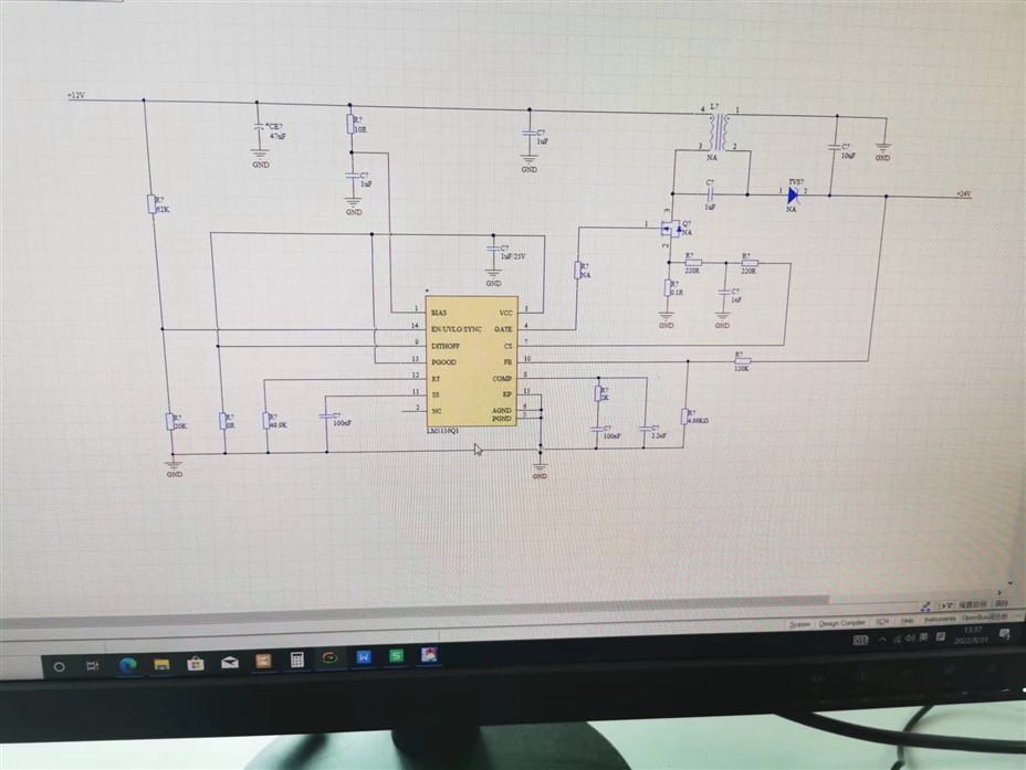
Other Parts Discussed in Thread: LM5155
Hi team,
Could you pls help review the Sch, looking forward to your reply, thanks a lot.
Vin:12V
Vo:24V@15W

This thread has been locked.
If you have a related question, please click the "Ask a related question" button in the top right corner. The newly created question will be automatically linked to this question.
Hi Hangjie,
Thank you for using E2E forums, May I know what is the Vin range of your design (min and max) alongside the Fsw?
Thank you
BR,
Haroon
Hi Haroon,
Sorry I forgot such important information, this is for a 12V battery in the car, Vin: 9~16V, thanks.
Hi Hangjie,
Thank you for your reply, regarding the review of the schematic.
1. The coupled inductance is suggested to be around 15 to 10 uh giving around 50 to 60% ripple and the capability of handling current of 4A rated current and saturation current much higher than that.
2. The sense resistor is way higher than what is suggested or recommended which is around 15m ohms and the Rslope can be around 1k ohms.
3. The minimum coupling capacitor value is supposed to be 1.3 uF, so 1uF seems a bit smaller than the recommended value.
4. The output capacitor with capacitance of 10uF will provide around 400mV ripple on the output voltage, so I would add some capacitors there.
5. The UVLO on is 5.9V and UVLO off is 5.4V for your Vin.
6. The compensation loop you can tweak using the LM5155/56 SEPIC calculator available on the TI website.
Hope this helps.
BR,
Haroon