


Hello, guys!
We have an SN2040 charger IC in our design. The very first thing I would like to know is whether this is an ancestor of the currently existing BQ24040 charger IC. Can you help me figure that out?
Here is how the charger is used in our system:
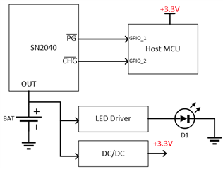
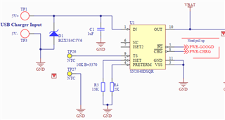
Our host MCU interfaces with the charger through PG and CHG pins (there are internal pull-up resistors that tie them to 3.3V). We also have an LED driver that we intended to use for playing battery charging and battery full patterns. Of course, we are aware that the current consumption of the LED driver + the rest of the system load should be below the termination threshold current. The charging current is set to ~40mA through a 13K resistor on the ISET pin. The charge termination current is set to 10% of the charging current (i.e. ~4mA) through a 2K resistor on the PRETERM pin.
We are able to properly detect the moment when the charger is connected and the charging process starts. Both PG and CHG pins go LOW. After that, we are not able to reliably and consistently detect battery full event (PG remains LOW and CHG goes from LOW to HIGH), even if we turn off the LED driver and minimize the current consumption of our system load.
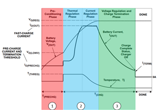
Is there anything we are missing about CHG pin behavior? It seems that sometimes CHG remains LOW even though the charging current is below the termination current. What should be the reason for that? For example, is it necessary to ALWAYS start the charging process from phase 2 or phase 1 (see image below) in order to have proper CHG pin behavior?
Thank you very much for your time and efforts. Looking forward to hearing from you.
Sincerely,
Bojan
