
- Ask a related questionWhat is a related question?A related question is a question created from another question. When the related question is created, it will be automatically linked to the original question.
Hello,
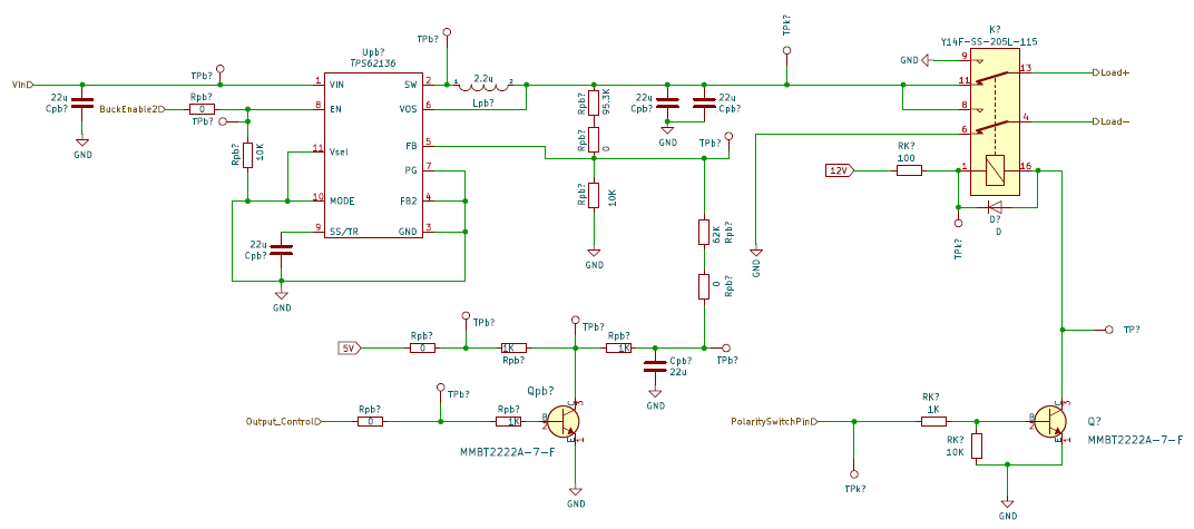
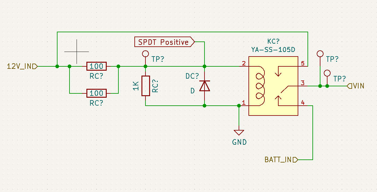
Our PCB currently has 2 of the Buck Converter Circuits below. Both VIN nodes of the buck converters are connected to the common port of a SPDT Relay. This SPDT relay serves us our power path to select either the battery voltage or a 12V Power Adapter. The relay (circuit shown below) is energize when the 12V Power Adapter is connected to our PCB. This makes it VIN switch from Battery Voltage (6-8.4V) to 12V. We have asked TI regarding this method of power pathing and the TI engineer said it should work (link below)
e2e.ti.com/.../bq25306-external-power-path-alternate-options
The current issue we are seeing is both buck converters currently are showing 0V in the output pin (SW) and in the feedback voltage pin (FB) even if there is a voltage input present (either the Battery Voltage or the 12V Adapter). We have also confirmed that the ENABLE pin is pulled High with 3.3V. This removes the possibility of having no output because of the EN pin. Does this indicate that the IC has been damaged internally?
We are also not seeing any internal shorts between the INPUT, OUTPUT and GND pins of the IC. Our output control pin which usually sets the output voltage from 0.7V to near VIN using the ICs 100% duty cycle is also functioning properly along with its circuit. We know that it was functioning before and we wanted to verify if the scenario we will be presenting below might be the cause of the failure.
As far as we recall, the last couple of things we did before we noticed the failure was switching the VIN of both buck converters from 12V to battery voltage and vice versa. We also did this while the ENABLE pin is high and our load was connected to the buck converter. Our load draws around 2-3A each (3A peak). We are mostly operating the buck converters at 100% duty cycle so the current draw is also similar. 4-6A total.
Could switching between Buck Input Voltage while at full load and ENABLE pin high cause both buck IC to fail and show these issues (0V output and FB pin)?
If not, do you think there might be other causes for the ICs to show this type failure?
If in best case scenario that it is not a IC failure but an operating condition, is there a way for it to be restored to its intended operating condition.
Let us know if there are other data you need from us to help in the failure analysis.
Buck Converter Circuit
Power Path Circuit
Thanks,
Deniel


