


Hello,
We want to know if the input current ripple we are seeing from the boost converter is the result of having a 2 wire brushless dc fan connected at the output/load.
Below is the circuit we have for the boost converter. It has an output set to 12V. The input voltage range is from 5.5 to 8.4V. The average current of the fan is around 300mA at 12V.

The output of the boost converter is connected to the FAN and LED driver circuit that consumes around 30mA. We are using a current probe to see the waveform of the FAN and boost converter input currents.
Below is the photo of the FAN current waveform coming from a 13V Power Supply. From datasheets of brushless fans, this is the expected waveform of a 2 wire brushless DC fan.
RMS current is around 376mA, peak to peak current of 456mA and a peak ripple current of 496mA. The values will be a bit lower when the input voltage is 12V.

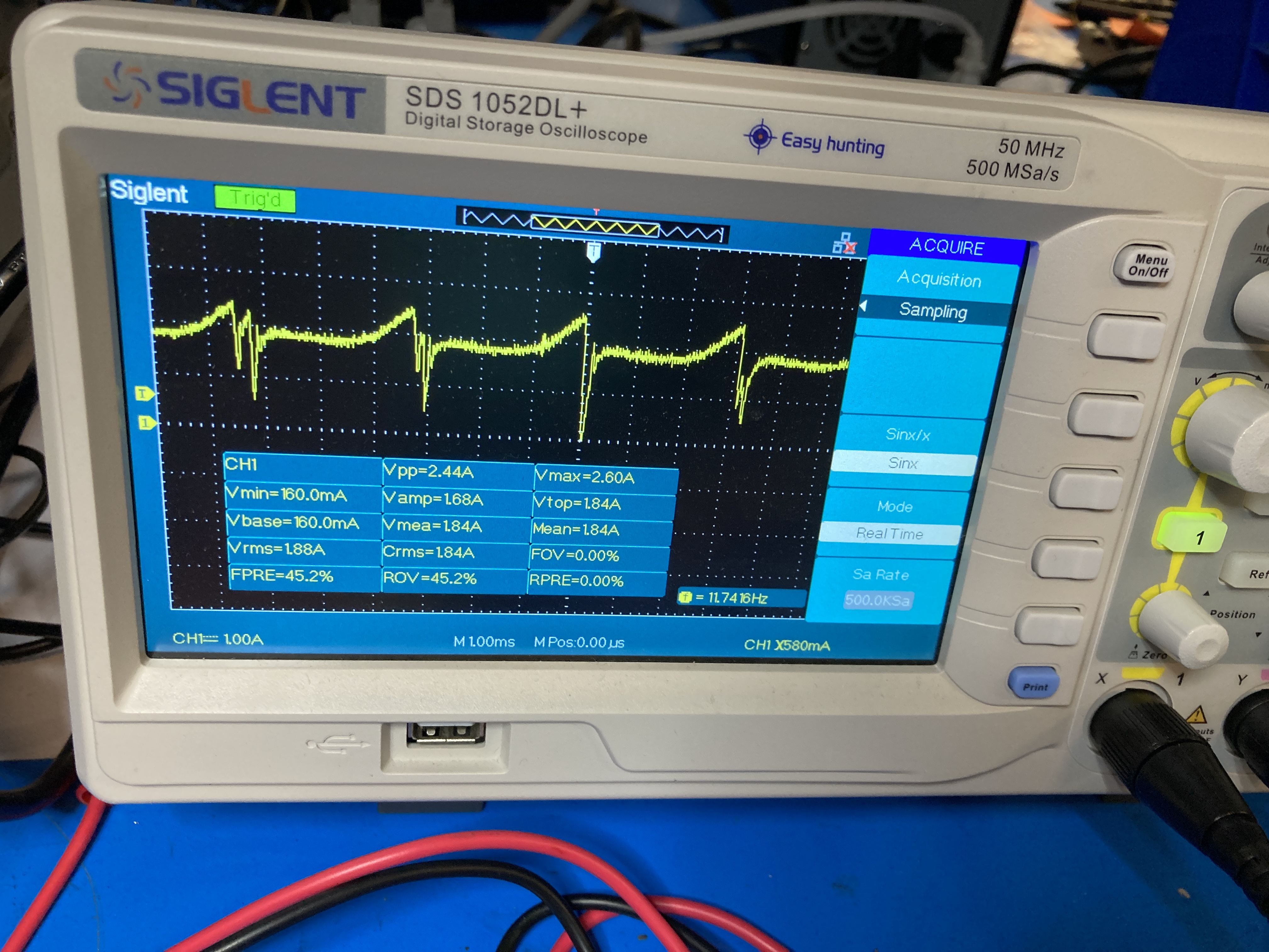
The PCBA we have has two of those boost converter circuits shown above. The way it connects to the FAN and LED circuit is via a cable of 6FT in length. Output of both boost converters is around 12.5V and the voltage when it reaches the fan/LED circuit is around 12V. Both Boost converter share the same input voltage. When powering ON our board with just the FANs and LEDs and the microcontroller (consumes only 150mA), below is the photo of the joined input current waveform both boost converters. The input current waveform is similar to the waveform of the FAN with higher current values because of the conversion ratio of a boost converter.
The RMS Current is 1.88A, Peak to Peak current is 2.44A and the Peak Current 2.6A. There is about 0.8A upper peak current in the input of the waveform. This is our main concern.
What we want to know is, Is this the typical behavior of a boost converter? Does the input current (before the input capacitor) follow the shape of the output current of load attached to it?
Is there a way to a have filtered version of the input current where it does not follow the shape of the fan current? Is there an additional circuit to add to improve the input current?
This current waveform (fan current shape) bleeds into the DC line. Is there a way to avoid it?
Let me know if you need more data or information regarding our design
Input waveform of both boost converters joined.
Best Regards,
Deniel

