This thread has been locked.

If you have a related question, please click the "Ask a related question" button in the top right corner. The newly created question will be automatically linked to this question.

TPS7B86-Q1: TPS7B86-Q1 damaged on two PCB boards

Part Number: TPS7B86-Q1
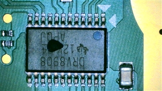
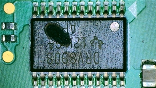
Other Parts Discussed in Thread: TEST2, , DRV8908-Q1

Hi TI engineer,

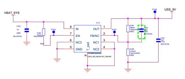
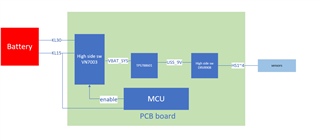
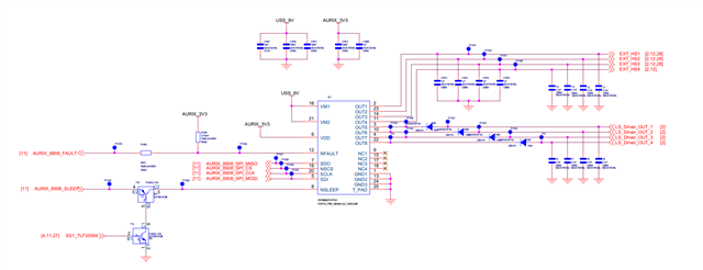
     In our project the  TPS7B8601QDDARQ1 is use for battery  conversion to 9V ,and the voltage range of battery is 9~16V(normally 14V)

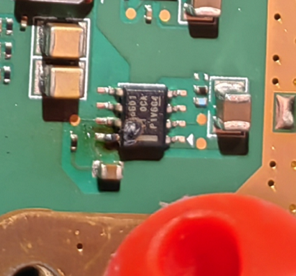
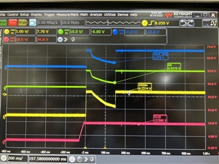
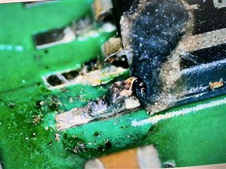
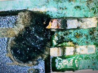
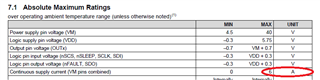
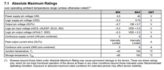
     We found 2 PCB boards encountered  TPS7B8601QDDARQ1 chip damage.  Both the two broken PCB are 8PIN(Battery IN)  damaged,The  TPS7B8601QDDARQ1 has thermal shutdown and current limit function,but the  power supply IN damaged,we want to know what can cause PIN8 damage?

  • Hi Yepeng,

    I do not see anything abnormal about the schematic. 

    Have you captured any startup waveforms? I'm curious to see what the input voltage looks like during startup. How is the battery connected? Is it always powered or is it a hot plug type of event? 

    Have you attempted an ABA swap test? 

    Can you verify that there is not a solder short between IN and the thermal pad on the bad boards?

    Regards,

    Nick

  • Hi Nick,

       Thanks for you reply.

        Before answering your question, let me introduce the architecture of our related circuit. you can see our block below,KL30 is power supply and KL15 is wakeup signal for wake system


       ① For the startup waveforms,you can refer to the picture below ,as you can see ,there is no voltage spike on the startup sequence。The initial fall edge is due to the MCU disabling VN7003(hige side switch),This phenomenon is normal.

       ②about battery connection,for our project, the TPS7B8601 Input is not always on,after KL15 waked  system,MCU will enable VN7003(high side sw),then TPS7B8601 will work

         ③ the TPS7B8601 has damaged,so we cannt do ABA test

         ④ We did X-ray test ,form X-ray test picture ,we didnt find any solder short to 8PIN(battery in),and you can see the flank of 8PIN was burned out .

    Damaged chip:

    Good chip:

  • Add some detailed photos of the damaged areas:

  • Hi Nick,

        We also did below test on good board:

         Test1:remove the on board load from USS_9V net, add a 20ohm resistor from USS_9V to GND,so the load current is 450mA ,the system can work steadily

         Test2:short  PIN1 USS_9V to GND ,the TPS7B8601 can trigger overcurrent protection.

     Look at the damaged chip,It looks like an overcurrent damage,We want to know if you have any good ideas for this overcurrent current loop


  • Hi Yepeng,

    Thank you for the information. I do not see a good reason why this kind of damage would happen; from the pictures it looks like there was current flowing through the pin and the device, and not outside of the device (i.e. a solder short as I mentioned). 

    Is there more downstream capacitance that needs to be charged during startup? If there is a large amount of downstream capacitance, there could be a problem with thermal dissipation during startup because the headroom is maximized when VOUT = 0V when startup initiates. This is a pretty rare condition so I consider this unlikely. 

    I understand that a full ABA test cannot be done since the device was destroyed, but have you tried putting a fresh device on a bad board to see if the part is destroyed in the same way? 

    When the damage was discovered, was it after powering the board several times or just once? Was the bad board operational at all before the damage was discovered?

    Regards,

    Nick

  • Hi Nick

        There is no more downstream cap be charged during startup,Sum of all cap on the USS_9V net is less than 15uF

        The damaged was discovered on the customer‘s car, so it must have been power on/off several times before damaged. Because in our manufacturing shop need do full test for our ECU.

        For the ABA test ,We do not intend to destroy the fault state now. If the theoretical analysis fails to give a proper reason, we will try to solder a good chip to the bad board

    Regards,

    Yepeng Zhang

  • Hi Nick ,

      We have a new discovery,As you suggested, we put a fresh chip to the bad board,after that the USS_9V is ok ,but the net HS1~4 still not work,so we found that the DRV8908QPWPRQ1 was also damaged. (In our ECU system ,The two chips are on opposite sides,There are a lot of heat sink glue on 8908 side. We removed those heat sink glue today, then we find 8908 damaged).And we found the problem with both bad boards is the same. TPS7B8601 and DRV8908 are damaged

       I'm not sure if this is helpful for you to analyze the problem, and I'm also not sure if you are responsible for DRV8909. If not, can you help to loop relevant people to this  question?


  • Yepeng,

    That is interesting. To me it doesn't explain what is damaging the TPS7B86-Q1 because I would expect the protection features to protect itself as well as downstream components. It is generally very unlikely for a modern LDO to be damaged thermally just from power dissipation in the device due to the load current and headroom because of the thermal shutdown features, and I don't see any reason that there would be a high-current event that is large enough to damage the device. I'll re-assign this post to the appropriate team to help support the DRV8908-Q1.

    Regards,

    Nick

  • Hi Nick

    Up to now, no TI engineer has replied to my question about DRV8908. Could you help me upgrade this problem? This is a BUG that happens in real cars and is very serious for us


  • Hi Yepen,

    Apologies for the delay, I have assigned one of our engineers that is the expert in automotive grade parts to look at this issue. Please allow him 24 hours to respond. 

    In the meantime, would you be able to confirm the following questions:

    1. Were the device operating specs and abs max specs in the datasheet violated?
    2. Were the design recommendations in the data sheet were followed? If not, how did they differ?
    3. Would you be able to provide us the schematic.
    4. Are you using the device in parallel mode operation? 
    5. I see you mentioned failure testing earlier, if so have you had a chance to do so again?
      1. What was the specific event that caused this failure including operating supply voltage, load current profile vs. time, scope-shots of the failure event will be crucial in understanding what happened.
      2. Was the failure repeatable in all the boards tested?
      3. Did you replace the blown out device and it blew up again consistently?
      4. What percentage of the boards tested failed?

    Best,

    Pedro Arango Ramirez 

  • Hi Pedro, 

       Thanks for your reply.

         For the questions:

    1.The device operaing  within the limits specified in the datasheet. 

    2. total recommendation were followed.

    3. schematic you can see below 

    4.The chip works independently on the PCB

    5. a. The chip damaged on real car,The electrical environment at that time was completely unknown to us

        b. As I mentioned above, it was on the car. There were two failure events (chip damage in two cars).

        c. I replace the TPS7B8601 and DRV8908 ,then the system can work  normally

        d. About 2/4000 pcs.

  • Hi, Yepen,

    Thank you for your feedback. If I understand your report correctly, your system works fine after replacing the damaged DRV8908-Q1. And part damage was happened in real car only.

    If you can reproduce the issue on your bench(not in the car), it should help finding root cause.

    -What is the motor current for each channels?  When turn on multi channels, what is the combined peak current (SPEC abs max 6A)

    -Thermal pad PCB layout is important for power device. Any chance DRV's thermal pad were soldered correctly?  DRV's thermal pad need to be connected to GND plane of PCB to have the proper thermal resistance.

    -While driving/stopping motors, is VM stable? or VM goes up?

    -Do you observe one of fault flag while operating?

    Above are just general tips. If you can reproduce issue on your bench, could you share what is the trigger for damage?  Then I will try to provide more comments.

    Thanks,

    regards

    Shinya Morita

  • Hi Shinya,

       You are right,our system works fine after replacing the damaged DRV8908-Q1. And part damage was happened in real car only.

       I have tried to reproduce the issue on our bench,but failed.  Do you have any good test cases to reproduce the problem?

        Our ECU not for motor but for Ultrasonic sensors, one DRV channel connected 4 sensors,and one sensor current MAX is 20mA ,typ is 5mA.

        DRV's thermal pad was connected to GND plane

         when Ultrasonic sensors on/off,  VM is stable

        The chip was damaged,so I can‘’t  observe any fault flag

         I'm sorry I didn't reproduce the problem in the lab

  • Hi Yepen,

    Thank you for your feedback. I understand your driving current is small and do not see the issue on the bench.

    Unfortunately I do not have idea what happens in real car. and how part is broken. 

    As you tried, hopefully you can reproduce the issue on your bench for further analysis...

    regards

    Shinya Morita 

  •  Hi Shinya,

        I would like to know if TI has any other cases of DRV8908 customer failure.


  • Hi Yepeng,

    Exceeding absolute max condition could cause device damage. 

    May not be your case but just ideas.

    - VM and GND are swapped.

    -Somehow some supply voltage applied on GND line.

    -Somehow high voltage applied on logic I/O or VDD pin.

    regards

    Shinya Morita

  • Hi Shinya,

        I will try to reproduce problem in our lab,if I successfully reproduce the problem,I will tell you as fast as possible

  • Hi Yepeng

    thank you for your update.

    regards

    Shinya Morita