Dear,
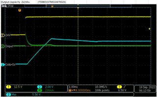
During start up, a short overvoltage appears at the output, cca 1V/3ms above 5V. The input voltage is 24V/+-10%. What is the reason for overvoltage? How can this be solved? Thanks in advance for the suggestions. Best regards, Petr.
Dear,
During start up, a short overvoltage appears at the output, cca 1V/3ms above 5V. The input voltage is 24V/+-10%. What is the reason for overvoltage? How can this be solved? Thanks in advance for the suggestions. Best regards, Petr.