This thread has been locked.

If you have a related question, please click the "Ask a related question" button in the top right corner. The newly created question will be automatically linked to this question.

TPS54618-Q1: TPS54618QRTERQ1: Irregular start up

Part Number: TPS54618-Q1

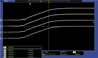
Vin: 3.3V, Vout : 1V, Load Max: 3.2A, Initial load: 20mA

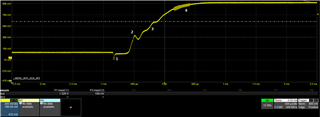
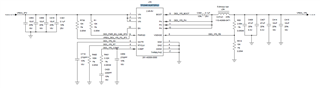
Observed irregular start-up voltage at the output, please find schematic and waveform below. Please help me understanding why this behavior is observed

  • Hi Saurabh,

    I'll have a look at the schematic and let you know my thoughts tomorrow at latest.

    Best regards
    Nelson

  • Hi Saurabh,

    I replicated your setup in our lab and got the following response:

    In my setup, I used a resistive load for the RLOAD traces and an electronic load for the ELOAD ones. The electronic load has a transistor-like behaviour. It starts pulling the desired IOUT at a given level of VOUT. On the other hand, the resistors will behave linearly. As you can see, I get an untypical behavior for the ELOAD with IOUT 3.2A.

    From your waveform I could tell the following:

    1. There was a remaining Vout from a past cycle that the device is trying to discharge.

    2. When Vout reaches 0.4V, a load is starting to draw current, which lowers Vout in a load transient manner.

    3. Subtle oscillating behavior can be seen, maybe caused by the past transient or an inductive load.

    4. A high frequency load might be activated at Vout around 0.8V, which leads to this noisy section of the Vout curve. 

    What do you mean with initial load and max load? What would be the shape of the IOUT in time during the start-up?

    What kind of load are you driving with the TPS54618-Q1?

    I hope this helps to clarify your queries.

    Best regards
    Nelson