This thread has been locked.

If you have a related question, please click the "Ask a related question" button in the top right corner. The newly created question will be automatically linked to this question.

TPS61196EVM-600: Cannot make 400mA

Part Number: TPS61196EVM-600

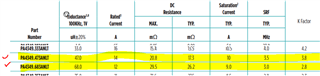
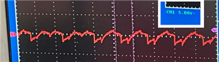
I need the 400mA design on my setup. I have changed R26 (ISET, 37.4K, 130mA) to 12.3K ( I believe it will make 400mA) based on ILED(400mA) =VISET(1.229)/R26(12300) x KISET(3992). Actually I fed 5% duty 60Hz PWM, and changed the R26 to different values, but it works up to around 280mA (R26 =  18K). I could not get a working condition either with R26 = 16K (it would be ILED = ~300mA). It works ok with R26 = 18K (it would be ILED = ~280mA). Please advise how to make the ILED = 400mA working condition on the TPS61196EVM-600 board?

  • Hi Sung,

    Please check two resistors:

    1. Resistance of R23

    This resistor together with R26 will determine the VIFBV, this voltage should be larger than 900mV if you want a 400mA output current.

    In the formula below, R10 is R23 on EVM, R11 is R26 on EVM. And to remind you, the 400mA output current is in pulse mode.

    2. Resistance of R24

    This resistor together with R26 will determine the LED_SHORT detection voltage.

    In the formula below, R12 is R24 on EVM, R11 is R26 on EVM.

    BR

    Patrick

  • Hi Patrick, Thanks a lot for the information. 

    BTW, V_IFBV is over 0.9V (calculated is ~1.5V) . And V_LED_SHORT is ~19V, so there is no issue to check 60V Vout LED short checking. I believe that those resistor values are ok...

    Well, I have one question. Actually the TPS61196EVM-600 design is 150mA, is there a possibility to change the inductor values to increase the current for the 300mA/400mA setting? I would like to confirm whether the inductor part (L1, 68uH, IHLP6767GZER680M1) is ok for driving 400mA to all six channels. If I need to change the inductor value for the 400mA design, then would you please recommend proper inductor parts? Please advise.

  • Hi Sung,

    What's your input voltage and output voltage (how many LEDs in series and what's the LED's VF)? We need to calculate the input current first before we choose an inductor.

    BR

    Patrick

  • Hi Patric, Oops... clicked the wrong button ... 'not resolved' .. I do not know how to go back...

    Input voltage is 12V, Vout is 60+V, there are 20ea LED (dual LED, 5.7V, 10ea), use all 6ch. Please advise. 

  • Hi Sung,

    That's fine, I'll continue to support you.

    The inductor on EVM is suggested to work with input current below 6A, but your working conditions require the input current larger than 12A. So I suggest you to choose an inductor with more current tolerance.

    Here is the datasheet of the inductor on EVM: IHLP6767GZER680M1

    BR

    Patrick

  • Hi Patric, then, do I need to use the low inductance parts? 10uH has 19A size... Will it be ok in terms of the TSP61196 part spec of the boost switch frequency range? 

  • Hi Patric, BTW, I will use 10% duty ... Would you please confirm the inductor part selection again with 10% duty of 400mA/6ch?

  • Hi Sung,

    Though your duty is only 10%, but with PWM dimming mode, the maximum current on inductor is still 12A. So I suggest you to choose a new inductor. And it will be better if the inductance remains the same as before.

    BR

    Patrick

  • Hi Patric, Got it. I found an inductor in Digikey, it is a Pulse inductor and I am considering using 47uH or 68uH. Would you please confirm whether the part can be a reasonable design of my application (400mA, 10ea 5.7V dual LEDs, 6ch, 12V in)? 

    https://www.digikey.com/en/products/detail/pulse-electronics-power/PA4349-473ANLT/7943172?s=N4IgjCBcoEwAwA4DsVQGMoDMCGAbAzgKYA0IA9lANogBsCABAK0ASIpALEk6wLqkAOAFyggAqgDsAloIDymALKFs%2BAK4AnQiAC%2BpeAgSoQGSDgIlyVcO3oBBEHxBCRE6XMXL1mrTpAxL-MgB3QjV6SXEAExU0QTI1ey0gA

  • Hi Sung,

    This inductor seems to be propriate. One more thing, is the inductor package suitable for your design? This one seems a little larger than which on EVM.

    BR

    Patrick

  • Hi Patrick, thanks a lot for your help. Yeah, I need to make a little larger pad for the new inductor. 

    BTW, I have another issue. Actually I have another type of LED bar (7ea, 3V LED) in my application. Today, I just replaced the LED bar (7ea LEDs) from the previous LED bar (20ea LEDs) TPS61196EVM-600 EVM HW setup. Well, observed the Vout is not properly set to ~21V range (I expected. that the Vout would be around 21V .. but it wasn't), and keep going up upto 60V... therefore the 7ea LED bar is not working at all. There are no changes, I kept the same HW setting. Would you please advise why the Vout is not landing at the ~21V and keep going up? And would you please advise how to fix the EVM design for the LED bar(7ea LEDs) supporting?

  • Hi Sung,

    Could you please send me the waveforms(screenshots of oscillator) when device starts up? And have you checked the LED bar?

    BR

    Patrick

  • Hi Patrick,

    Sorry for the late reply. Actually when I reduced the OVP level around 30V from 60V, then the 7ea, 3V LED module works ok. 
    I am not sure whether the adjusting OVP level is the right solution for the 7ea, 3V LED module. Please advise.

    BTW, there is another critical issue on the 10ea 5.7V dual LED module. When I feed 10% duty 60Hz PWM, there is a flickering issue. Well, the Vout (~60V) voltage ripple AC Vp_p (peak to peak) shows a jumping waveform randomly around within 5v range, as the result that there is the LED flickering behavior. Refer to the attached captured Vout AC waveform.

    The EVM board has been modified below three resistors to get a 50mA setting.

    R7 : 220K

    R23 : 100K

    R26 : 100K

    Yeah, I know the part required the min 90Hz PWM, but we need 60Hz PWM in our application.

    Is there a solution to reduce the Vout (~60V) ripple Vp_p @ 60Hz PWM mode?

    Thanks,

    Sung

  • Hi Sung,

    Our experts for this issue are currently celebrating the Chinese Golden Week holiday, they will respond to you next week.

    Regards,

    Dave

  • Hi Sung,

    I doubt that when device is powered on, if you set the OVP level too high, it might cause the REF pin voltage hard to be higher than OVP pin. This might be the reason that device didn't work well. So in previously reply I suggested you catch the screenshot of start-up waveforms.

    From your figure, is the peak-to-peak voltage about 5V? What's the total output capacitance?

    As for visible flickering with 10% duty 60Hz PWM, I don't think there is a method to reduce it......

    BR

    Patrick

  • Hi Patric, 

    When I make 120Hz PWM, 10% duty, then there is no LED flickering issue. In terms of the OVP and REF voltage levels, they wouldn't be different.. Would you please advise how to make a good combinated setting at 60Hz PWM case, if there are?

    And I am using your EVM board, there is 100uF on C2. 

    Thanks,

    Sung

  • Hi Sung,

    I think 60Hz is very easy for human eyes to see flickering. If the brightness is lower, the flickering is even worse. What's your application with 60Hz condition?

    BR

    Patrick

  • Hi Patrick,

    I would like to know what is the difference between Vout 30V and 60V since there is no LED flickering issue with 30V. The PWM input setup is the same setting to both inputs; 60Hz 10% duty. 

    And when increasing the PWM frequency at the 60V setup, then there is getting better behaviour and then no flickering symptom after 90Hz. 

    Would you please advise whether there is a possibility to improve the 60V setup to be a better situation, less flickering or up to the no flickering result? 

    Thanks,

    Sung

  • Hi Sung,

    Could you share waveforms about ILED and VOUT at 30V and 60V?

    In previous reply you said you have a "10ea 5.7V dual LED module", is it the same one in the latest 60Hz test? I'm a little confused about which module with what test setup and in which test.

    In case there is any misunderstanding between us, could you please give me a summary of all your tests, including test setup, LED module, and phenomenon etc. So that I can run these tests on EVM myself and give you better support.

    BR

    Patrick