This thread has been locked.

If you have a related question, please click the "Ask a related question" button in the top right corner. The newly created question will be automatically linked to this question.

TPS63020: Start-up, VINA and ENABLE

Part Number: TPS63020

Hi,

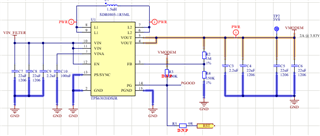
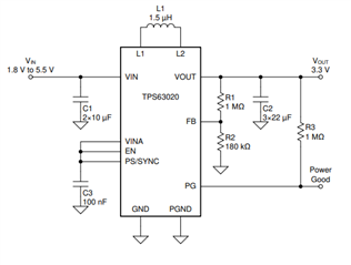
I'm using the following configuration for the power supply connected to a ~50ohm load.


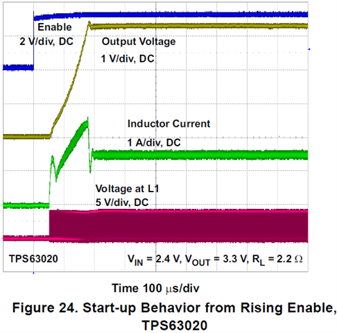
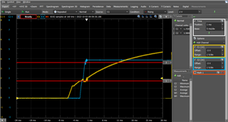
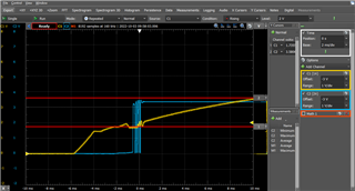
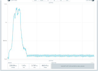
During some preliminary tests in regard to the DCDC converter  start up, I'm getting the following curves for the Vin and Vout  lines and a in-rush current profile.


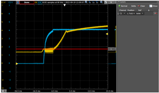
As visible, the approach used for the EN's connection differs from the datasheet ( it was connected directly to VIN instead of VINA), so instead of waiting for a more stable input voltage, after turning on the system, the DCDC is enabled as soon as the input voltage is 1.2V.

 - Does this indicates that, as the converter is enabled and the output capacitors are seen as short circuit during this initialization, the converter goes to PWM mode (Iout>100mA)? 

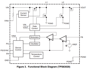
- The illustrated connection show that EN is connected to VINA where an internal resistor is present between VIN and VINA. What is its value?
- Is the purpose of this configuration to create that enable delay and mitigate this initialization behavior?


Thank you for your attention.


  • Hi   Fabio,


     - Does this indicates that, as the converter is enabled and the output capacitors are seen as short circuit during this initialization, the converter goes to PWM mode (Iout>100mA)? 

    that is right, you can see the picture below as ref.

    the resister internal is around hundreds, and the purpose of this configuration is to make a cleaner supply for block internal. you can take this as a RC filter from Vin to VINA.

    also, you are right about the delay of EN, but i think that is not our initial goal.Joy

    Regards

    Tao

  • Hi,
    Thank you for your reply.
    Considering the previous circuit configuration and applying a current load of ~350mA at the converter's output, I'm getting the following behavior on the following signals:
     - Vin vs Vout
     - Vin vs PGood

    From my understanding, as the EN pin is directly connected to Vin, the converter is enabled when the input voltage is still unstable.
    An RC filter applied to the EN pin could be an option to create a soft start and wait for a more stable input voltage.

    What is the EN pin threshold and tolerances for the timing calculation?

    Is there any further recommendation?

    Thank you for your attention

  • Hi   Fabio,

    that is right, an RC filter for EN can help to make the device start to switch after input voltage stable enough.

    the threshold of EN high is a 0.4-1.2V.  there is a big variation between devices.

    but also, there is a delay from EN high to first switching pulse, around 100us.

    so, i think we can use 0.4V as EN high for filter design. than we can make device always start to switching after input is stable.

    Regards

    Tao

  • Hi Tao,

    Thank you for your prompt reply.
    I'll just mark this issue as resolved.

    Fabio

  • Hi  Fabio,

    Thanks Grin

    Regards

    Tao