This thread has been locked.

If you have a related question, please click the "Ask a related question" button in the top right corner. The newly created question will be automatically linked to this question.

Designing for low current draw

Part Number: TPS54386PWPR
Other Parts Discussed in Thread: TPS54386

I was taking a look at the power regulation circuit on our PCB because I needed to decrease the footprint and I noticed that it had been significantly over-designed. It looks like whoever designed the circuit originally just copied one of the reference designs and called it a day, even though it did not match our specifications, so I went ahead and did the math necessary to redesign it. The catch is that our expected current draws are very small; on the order of 100-200mA per output, so the math gave me results that I'm not sure are correct. Does the following schematic make sense or am I missing something? The circuit takes 24V in and outputs 5V @ 155mA and 3.3V @ 100mA.

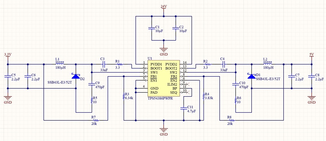
As a final note, I am aware that the TPS54386 is overkill for our design; unfortunately we've already consigned parts for 1000 production units so we're stuck with it for at least a while.

  • Hi Jeffrey,

    My colleague will give you response later!

    BRs

    Zixu

  • Hi Zixu,

    Any update on this?

  • Hi Jeffrey,

    Sorry for late response and thanks for reaching out. 

    Is the schematic shown above the from original overspec design or the updated one?

    Thanks!

    BRs

    Lucia

  • Hi Jeffrey,

    It's suggested that you don't need that large inductor. Please follow the equation shown below:

    Here the maximum output current means 3A, we don't need to use 0.1-0.2A. And please kindly reselect Cout based on the updated inductor value.

    Anything unclear, kindly let me know. Thanks!

    BRs

    Lucia

  • Hi Lucia,

    The design I included is the updated one. Also, if I understand you correctly, I should be using 3A as the maximum output current, even though we only expect to draw 0.1-0.2A. Is that correct? In that case, can I source an inductor that's only rated for the actual current we expect to see or do I need to find one that can handle 3A? If I ground ILIM2, can I use 1.5A as the maximum output current for that circuit? And wouldn't that mean I need to use 4.5A for the maximum for output 1 since that's where the current limit threshold is?

  • Hi Jeffrey,

    My colleague Lucia will give you reply by tomorrow!

    BRs

    Zixu

  • Hi Jeffrey,

    Yes, you are right. But please kindly check the rated current and saturation current according to the inductor rms current and peak current.

    Thanks

    BRs

    Lucia

  • Hi Jeffrey,

    I mean that in this equation, we recommend to use 3A*K as the peak to peak ripple. And for the current rating, you need to consider the rated current, the saturation current and also the current protect limit. This ensures that the inductor does not saturate even during a short circuit on the output. When the inductor core material saturates, the inductance falls to a very low value, causing the inductor current to rise very rapidly.

    BRs

    Lucia

  • Hi Lucia,

    If I'm calculating this correctly (so using 600mA as the maximum ripple but 100mA as the maximum output current), I can reduce the inductors to 15uH, with a ripple current of 475mA for 5V and 357mA for 3.3V. This is significantly larger than my expected current draw; is that going to be a problem?

    Also, it looks like that would mean my saturation currents are 338mA and 279mA, so I'm looking for a 15uH inductor with rated current of at least 100mA and a saturation current of at least 340/280mA. Additionally, I'd need 47uF of output capacitance. Does that make sense?

  • Hi Jeffrey,

    My colleague Lucia will give you reply by next Monday!

    BRs

    Zixu

  • Hi Jeffrey,  

    1. It not only depends on the rated current and saturation current of the inductor but also you need to consider the current protection limit. For example, when the device enter current protection mode,  the saturation current rating of the inductor is at least as large as the protect current limit. This ensures that the inductor does not saturate even during a short circuit on the output. When the inductor core material saturates, the inductance falls to a very low value, causing the inductor current to rise very rapidly. If you want this current protection function work well, please also select the inductor based on this. 

    2. What's more, in the equation, you can use 3A*K as the peak to peak ripple.

    Anything unclear, please kindly let me know.

    BRs

    Lucia

  • Hi Lucia,

    I understand the issues caused by inductor saturation; that part makes sense. What's confusing me is that the example in the datasheet calculates a saturation current of 2.25A for both outputs, despite the nominal overcurrent limit for output 1 being fixed at 4.5A. Is that not correct? Or am I missing some other part of the circuit that prevents saturation in the case of a short?

    Also, is it a problem that the peak-to-peak ripple is greater than my maximum expected current?

    Thanks,

    Jeffrey

  • Hi Jeffrey,

    My colleague Lucia will give you response by next Monday!

    BRs

    Zixu

  • Hi Zixu,

    My apologies, I was out of town for the past two days. I was wondering if Lucia might be able to answer my questions by the end of this week?

    Thanks,

    Jeffrey

  • Hi Jeffrey,

    Due to the vacation of national holiday, my colleague Lucia will give you response after 10/8.

    BRs

    Zixu

  • Hi Jeffrey,

    (1) What's confusing me is that the example in the datasheet calculates a saturation current of 2.25A for both outputs, despite the nominal overcurrent limit for output 1 being fixed at 4.5A. Is that not correct?

    --- From the datasheet section 9.2.1.2.2 Inductor Selection, you can see that the calculation of inductor saturation current is based on the maximum peak inductor current at maximum load. I should say this is a must and most strict requirement that minimum saturation current rating of 2.25 A is required. When choosing the inductor, the inductor saturation current must not be less than the maximum peak inductor current. When you look at overcurrent protection, ideally, the saturation current rating of the inductor is recommended to be as large as the high-side switch current limit.

    (2) Is it a problem that the peak-to-peak ripple is greater than my maximum expected current

    --- When the load is light and the peak-to-peak ripple is greater than maximum expected current, the device will enter discontinuous mode and it can still work well.

    Hope this helpful. Anything unclear, kindly let me know. Thanks!

    BRs

    Lucia

  • Hi Lucia,

    That helped a lot. I will use 2.25A as my saturation current. One last question: You mentioned using 600mA for the ripple current; Figure 23 in the datasheet includes response curves for 200mA and 400mA as well. Can I use 200mA as my ripple current since that is closer to my expected current draw? It would boost my inductance to ~33uH, which is still significantly less than the 180 in the schematic I posted originally.

  • Hi Jeffrey,

    It depends on your application. Lower inductance corresponds to faster transient response, smaller DCR, and reduced size. But too low of an inductance can generate too large of an inductor current ripple such that over current protection at the full load could be falsely triggered. It also generates more inductor core loss since the current ripple is larger. Typically, we would recommend K to be 20%-60%. You can use 200mA ripple current according to your application if the size of 22uH can meet your requirement. Please also check this on your evaluation board. Thanks!

    Anything unclear, kindly let me know. Thank!

    BRs

    Lucia

  • Hi Jeffrey,

    Please kindly check whether the size of 33uH can meet your requirement. Sorry for 22uH from last reply which is a typo. Thanks!

    BRs

    Lucia

  • Hi Jeffrey,

    I will close this threat first. Please re-open it if there is any future question.

    BRs,
    Lucia