This thread has been locked.

If you have a related question, please click the "Ask a related question" button in the top right corner. The newly created question will be automatically linked to this question.

LM51561-Q1: SEPIC design troubleshooting

Part Number: LM51561-Q1

Hi team,

In the current design I am trying to use the LM51561-Q1 as a SEPIC controller.

The specifications are:

  • Vin range = 7 to 17 V
  • Vout = 12 V
  • Iout max = 2 A (nominal 0.6 A)
  • switching freq = 2.2 MHz

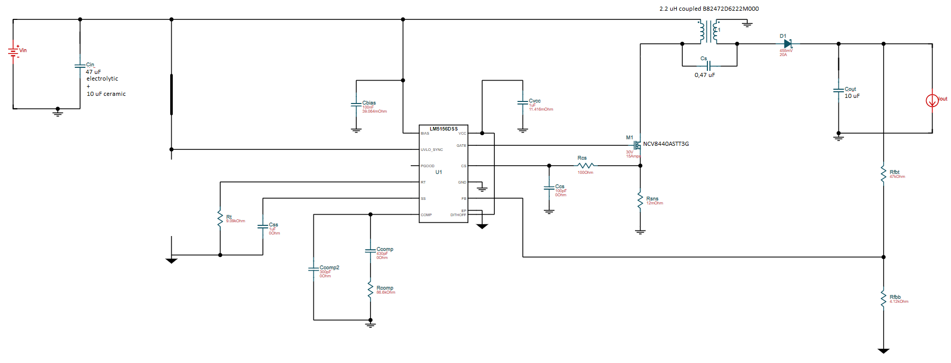
The schematics are the following:

/resized-image/__size/1920x1080/__key/communityserver-discussions-components-files/196/0435.sepic.png

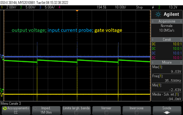
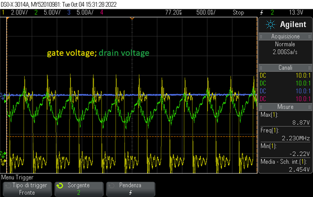
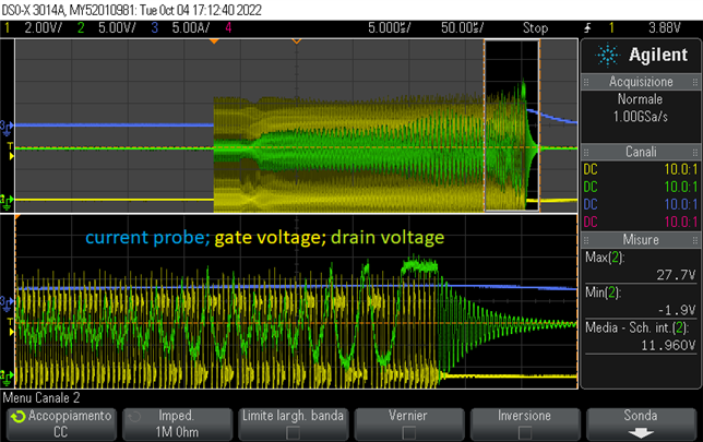
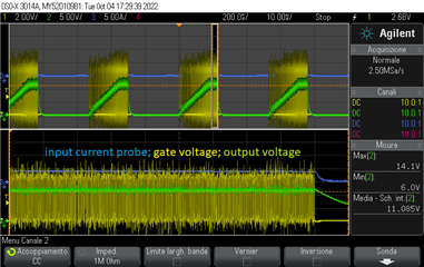
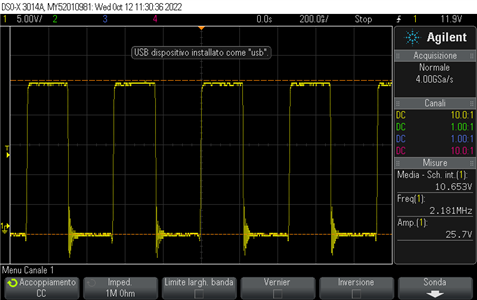
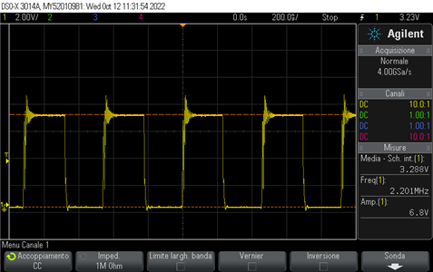
The problem I am having is that when the load (20 Ohm resistor) is connected, the output voltage drops and the bench power supply goes in current limit mode due to the large currents flowing in the MOS.

The steps I am planning to follow to get a working design are:

  1. Increase coupled inductors values (up to 10 uH)
  2. Increase input and output capacitances
  3. Lower the switching frequency
  4. Add UVLO resistors
  5. Tune CS pin resistors and SS pin capacitances

I would like to have your feedback about it.

Best regards,

Luca

  • Hi Luca,

    thank you for using the E2E forum

    Can you please check the saturation current of the inductor.

    With a output load of 0.6A this should be at least 1.6A better 2A

    When targeting up to 2A then go for 4.5A

    I also think the coupling cap is quite low would here go more for 1.6uF

    Once ensured that your power supply can handle there required current you can also check with a lower load the signal on the the sense resistor on check if this is matching the expected level.

    Best regards,

     Stefan

  • Hi Stefan,

    Thank you for the quick reply.

    I have verified that the saturation current of the inductor is > 2A (5,6 A).

    I have not tried different coupling capacitors values yet, I will test it as soon as possible.

    The power supply can handle the required current, I will verify the drop on the sense resistor.

    I don't have the hardware available at the moment, I will report in the next few days.

    Regards,

    Luca

  • Hello Stefan,

    I started testing the SEPIC circuit properly. As you recommended I increased the coupling capacitor to 4.7 uF. I have also increased the coupled inductor to 10 uH (B82472D6103M000).

    I attach the behavior of the circuit with and without load.

    I was not able to measure the voltage drop on the current shunt due to the high noise.

    What would you recommend to do next?

    Regards,

    Luca

    --------------------

    The behavior of the circuit without load is the following:

    If I connect a 36 Ohm load (0.33 A) the output is not stable:

  • Hello Luca,

    Can you please check as well the input voltage at the input capacitors? 

    Best regards,
    Brigitte

  • Hello Brigitte,

    Sorry for the late reply, these weeks are really busy.

    We managed to solve the problemsby replacing the MOS with a faster one (looking at the drain waveform we assumed that the MOS was too slow).
    So we chose a MOS with lower gate charge to reduce transition times and reduce switching power dissipation and with lower ON resistance to reduce conduction power dissipation.

    I have attached the waveforms with the new MOS.

    Input voltage:

    Drain voltage:

    Gate voltage:

    Output voltage:

    Regards,

    Luca

  • Hello Luca,

    Great to hear that you have solved the issue. Thank you for informing us, so I will close the thread now. But you can post below if there are further questions.

    Best regards,
    Brigitte