This thread has been locked.

If you have a related question, please click the "Ask a related question" button in the top right corner. The newly created question will be automatically linked to this question.

BQ76940: I2c

Part Number: BQ76940
Other Parts Discussed in Thread: BQ76920, BQ76930, MSP430F247

Hi,

I am designing BMS board firmware using mspf247 as main MCU, bq76940 as  AFE to monitor battery. The communication interface between these two devices is I2C.

What troubled me is with each new pcba board while power on for the first time, the series cell voltages, pack voltage are read out correctly.

After running for a while, the readings are getting messed up. And susequently debugging shown the data reading is not right.

The basic programm logicals are to configuring bq76940 continuously monitor cell voltage, packvoltage periodically, and the alert signal will trigger an interrupt every 250ms,

set corresponding flag in the isr routines.

In a task the voltages and coulomb will be read.

Below   i posed some code for reference,

void I2C_Initialise()
{
UCB0CTL1 |= UCSSEL_2+UCSWRST; // enable SW reset, use SMCLK as USCI clock source
//UCB0CTL1 |= UCSSEL_1+UCSWRST; // enable SW reset, use ACLK as USCI clock source
UCB0CTL0 = UCMST + UCMODE_3 + UCSYNC; // set to I2C master mode
UCB0BR0 = 10; // 92.16KHz @0.9216MHz of SCLK, make sure SCLK does not exceed 100KHz
UCB0BR1 = 0;
UCB0I2CIE = 0; // disable nack, stop condition detected, start condition detected, arbitration-lost interrupts
IE2 &= ~(UCB0TXIE + UCB0RXIE); // disable Tx&Rx interrupts
UCB0CTL1 &= ~UCSWRST; // release from reset state
bqI2CError = FALSE; // clear i2c fault error flag
bqI2CStatusReadError = NO_SIGNIFICANCE;
}

// 76940 initialzation

void BqInitialisebqMaximo(void)
{
uint16_t count = 0;
bqCoulomb = 0;
bqTotalCoulomb = 0;
bqBalanceIndex = 0;
RAM_CELL_BALANCE=bqBalanceIndex;

//BQ76920/BQ76930/BQ76940 need 250ms/400ms/800ms from SHIP-to_NORMAL transition to first read operation, datasheet, page 21.
//ALERT will be set in approx. 990ms after SHIP-to-NORMAL transition.
//Stay here for the alert to be set.
while(TRUE)
{
delay_1ms(1);
count++;
if(BqIsAlert() == TRUE)
{
break;
}
else
{
if(count >= 1200)
{
//MCU is powered but in 1s ALERT is not set ...error
break;
}
}
}

//dummy write command to BQ
BqSetRegisterByte(SYS_STAT, 0xff); //clear alert
//tt=BqGetRegisterByte(SYS_STAT);


//Set CC_CFG to recommended value of 0x19
//tt=BqGetRegisterByte(CC_CFG);
BqSetRegisterByte(CC_CFG, 0x19);
//tt=BqGetRegisterByte(CC_CFG);

//read adc gain and offset
bqAdcGain = BqGetAdcGain();
bqAdcOffset = BqGetRegisterByte(ADCOFFSET);

//set OV_TRIP and UV_TRIP according to threshold setting and gain+offset info
OVPThreshold = logic.regbyte_ov_trip;
BqSetRegisterByte(OV_TRIP, BqTripConversion(OVPThreshold, bqAdcGain, bqAdcOffset));
//tt=BqGetRegisterByte(OV_TRIP);

UVPThreshold = logic.regbyte_uv_trip;
BqSetRegisterByte(UV_TRIP, BqTripConversion(UVPThreshold, bqAdcGain, bqAdcOffset));
//tt=BqGetRegisterByte(UV_TRIP);

//setup protections
//SCD
regPROTECT1_t protect1;
protect1.Protect1Bit.SCD_DELAY = SCDDelay;
protect1.Protect1Bit.SCD_THRESH = SCDThresh;
protect1.Protect1Bit.RSNS=1;
BqSetRegisterByte(PROTECT1, protect1.Protect1Byte);
//tt=BqGetRegisterByte(PROTECT1);

//OCD
regPROTECT2_t protect2;
protect2.Protect2Bit.OCD_DELAY = OCDDelay;
protect2.Protect2Bit.OCD_THRESH = OCDThresh;
BqSetRegisterByte(PROTECT2, protect2.Protect2Byte);
//tt=BqGetRegisterByte(PROTECT2);

//OVDelay,UVDelay
regPROTECT3_t protect3;
protect3.Protect3Bit.OV_DELAY = OVDelay;
protect3.Protect3Bit.UV_DELAY = UVDelay;
BqSetRegisterByte(PROTECT3, protect3.Protect3Byte);
//tt=BqGetRegisterByte(PROTECT3);

//setup system controls
regSYS_CTRL1_t ctrl1;
ctrl1.SysCtrl1Bit.ADC_EN = logic.regbit_adc_en;
ctrl1.SysCtrl1Bit.LOAD_PRESENT = 0; //read-only bit
ctrl1.SysCtrl1Bit.SHUT_A = 0; //do not go to SHIP mode
ctrl1.SysCtrl1Bit.SHUT_B = 0; //do not go to SHIP mode
ctrl1.SysCtrl1Bit.TEMP_SEL = logic.regbit_temp_sel; //ExternalThermistor; //0 = die temp; 1 = thermistor temp
BqSetRegisterByte(SYS_CTRL1, ctrl1.SysCtrl1Byte);
//tt=BqGetRegisterByte(SYS_CTRL1);

regSYS_CTRL2_t ctrl2;
ctrl2.SysCtrl2Bit.CC_EN = logic.regbyte_sys_ctrl2.SysCtrl2Bit.CC_EN; //0 = disable continuous reading; 1 = enable
ctrl2.SysCtrl2Bit.CC_ONESHOT = 0; //0 = no action; 1 = trigger one shot reading
ctrl2.SysCtrl2Bit.DELAY_DIS = 0; //0 =normal delay; 1 = no delay (250ms)
ctrl2.SysCtrl2Bit.CHG_ON = 0; // 0 = CHG FET OFF; 1= CHG FET ON
ctrl2.SysCtrl2Bit.DSG_ON = 0; //0 = DSG FET OFF; 1 = DSG FET OFF
//ctrl2.SysCtrl2Bit.WAKE_EN = 0; //not present in BQ76930
//ctrl2.SysCtrl2Bit.WAKE_T =0; //Not present in BQ76930
BqSetRegisterByte(SYS_CTRL2, ctrl2.SysCtrl2Byte); // in initialization turn off chg and dsg
//tt=BqGetRegisterByte(SYS_CTRL2);

regSYS_STAT_t status;
status.StatusByte = BqGetRegisterByte(SYS_STAT);
if(status.StatusByte & STAT_FLAGS)
{
//device status flag(s) is set by some reason, clear it.
BqSetRegisterByte(SYS_STAT, STAT_FLAGS);
}
}

#pragma vector=PORT1_VECTOR
__interrupt void isr_port_1(void)
{
if (P1IFG & BIT5)
{
// read SYS_STAT byte
bqI2CError = NO_SIGNIFICANCE;
bqStatus.StatusByte = BqGetRegisterByte(SYS_STAT);
bqI2CStatusReadError = bqI2CError;
BqSetRegisterByte(SYS_STAT, STAT_CC_READY);
P1IFG &= ~BIT5; // clear interrupt flag
}
}

void taskA(void)
{
uint8_t i;
static uint16_t time_out_counter =0;

time_out_counter++;

if(bqI2CStatusReadError == FALSE || time_out_counter > 100)
{
if (bqStatus.StatusBit.DEVICE_XREADY == TRUE)
{
//for this fault data can not be trusted
fault.BQ.bit.XREADY = TRUE;
}
else
{
// 250ms cycle completed
if(bqStatus.StatusBit.CC_READY == TRUE)
{
// read Coulomb counter
int32_t cur;
int16_t tmp;
tmp = BqGetCoulombCounter();
if(bqI2CError == FALSE)
{
bqCoulomb = tmp;
bqTotalCoulomb += bqCoulomb;
//current is calculate here, in BQ current > 0 - chargeing
cur=(int16_t)((bqCoulomb*8.44)/(Rsense)); // 1uA unit
cur=(-cur/100000); // in unit of 0.01A
RAM_Shunt_I=cur;
}
else
{
//i2C error
fault.BQ.bit.i2c = TRUE;
}

// read cell voltage
uint16_t min=65535, max=0;
for(i=0; i<NUMBER_OF_CELLS;i++)
{
tmp = BqGetCellVoltage(i+1);
if (bqI2CError == FALSE)
{
RAM_Volt_Cell[i] = tmp;
if (RAM_Volt_Cell[i]<min)
{
min=RAM_Volt_Cell[i];
LowestCellIndex = i;
}
if (RAM_Volt_Cell[i]>max)
max=RAM_Volt_Cell[i];
}
else
{
//i2C error
fault.BQ.bit.i2c = TRUE;
}
}
RAM_HighestVolt=max;
RAM_LowestVolt=min;
if (RAM_HighestVolt > RAM_MaxVolt)
{
RAM_MaxVolt = RAM_HighestVolt;
}
if (RAM_LowestVolt < RAM_MinVolt)
{
RAM_MinVolt = RAM_LowestVolt;
}

if (!(Flag_Work&Flag_After1rstReadVolt))
{
Flag_Work|=Flag_After1rstReadVolt;
Soc_FirstDataAvailable((U16*)RAM_Volt_Cell);
}

// read pack voltage
tmp = BqGetPackVoltage();
if(bqI2CError == FALSE)
{
bqPackVoltage = tmp;
RAM_SUM_Cells = tmp;
}

  • Hey Kevin,

    We have software examples that you could take a look at to possibly help you debug. Beyond that, you could try replacing the IC with another one to see if the issue persists. If it is software isolated I highly recommend you take a look at the example code.

    Thanks,
    Caleb

  • Thanks Perez, I am new to this forum, where i can find the example code?

  • Hey Kevin,

    No worries. You can find the example code on the product page. Here's the link. https://www.ti.com/product/BQ76940#software-development Scroll down until you find the "Software Development" tab.

    Thanks,
    Caleb

  • Hi,

    I follow your suggestion, the demo code of i2c is the same as my code used, I simplified my firmware logical by doing the following, after power on,

    I2c is set to master mode, use SMCLK as usci clock source, the clock frequency is at 92160, wait for about 1200ms, then start to write to CONTROL 1, and CONTROL2 registers, and read back of the setting of these two registers,

    for(;;)
    {
    //LPM3;

    if(Flag_1MS == TRUE)
    {
    Flag_1MS = FALSE;
    //taskHandler(); //run task handler every 1ms
    //setup system controls
    regSYS_CTRL1_t ctrl1;
    ctrl1.SysCtrl1Byte=0x10;
    BqSetRegisterByte(SYS_CTRL1, ctrl1.SysCtrl1Byte);
    sys_reg_cotr1=BqGetRegisterByte(SYS_CTRL1);

    regSYS_CTRL2_t ctrl2;
    ctrl2.SysCtrl2Byte=0x40;
    BqSetRegisterByte(SYS_CTRL2, ctrl2.SysCtrl2Byte);
    sys_reg_cotr2=BqGetRegisterByte(SYS_CTRL2);

    RST_HWWDT();
    }

    for control 1 register i wrote value of 0x10, and read back as 0x98,

    for control 2 register i wrote value of 0x40, and read back as 0x98,

    Please help me to find a clue,

    Thanks!

  • Hi Kevin,

    Is this issue different than what you originally were reporting? This seems like a different issue - were you having trouble writing to these control registers in your previous code?

    Best regards,

    Matt

  • Hi Matt,

    Yes, there are troubles to write to these control registers with my original code too. 

    In my original code,for each new pcba, the first time power on, i think the writing to these control registers were successful, because i can see all 11 cell voltages, and pack voltage are read back correctly.  Only after running for a while, i power off the bms and power on it again, the reading of voltages are not right any more.

    I debugged the 76940 initialization process and found writing to these control registers and reading back of them are quite different.

    So the original code and the new simplified code have the same issue.

    Those control registers were not set right, the 76940 can not work right as expected.

    Here are the original code logical,

    set SYS_CTRL1 register with ADC_EN on. set SYS_CTRL2 with CC_EN on.

    The 76940 will toggle alert signal every 250ms, the alert signal will trigger an interrupt for MCU.

    The SYS_STAT register will be read , and cleared in the interrupt routine.

    Actual reading of votages and coulomb count will be carry out in a task.

    Thanks

  • Hi Kevin,

    This is not a common issue. I suggest capturing on a logic analyzer with your code to see what might be happening. Maybe you can compare this by connecting an EVM to the GUI and capturing on the logic analyzer for comparison.

    Regards,

    Matt

  • Hi Matt,

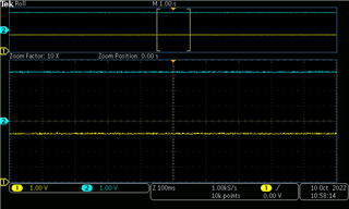
    I follow your suggestion, and capture wave form like this

    No signals at al

    l

    Any suggestion?

  • Hi Kevin,

    This cannot be caused by the BQ76940 device since the host should be driving the communications. The BQ76940 will never control the I2C clock, only the host.

    Regards,

    Matt

  • Hi Matt,

    I know the BQ76940 is drived by host, in our design the msp430F247 MCU. I have tested the BQ76940 on my board by using TI evaluation software, the BQ76940 is working well. It is sure the problem is in mastor side. When sending a write command to BQ device, the I2C seems generating start bit and transmission of slave address successfully, but it is always failed to transfer data.

    According to I2C module description on MCU user guide,  the UCB0TXIFG flag should  be set when a byte of data is sent out, but it is never set, why?

    The I2c module looks like not working as it should be.


    static int8_t I2CSendBytes(uint8_t I2CSlaveAddress, uint8_t *pDataBuffer, uint16_t ByteCount, uint16_t *pSentByte)
    {
        uint16_t DelayCounter = 0;
        uint16_t NumberOfBytesSent = 0;
        uint8_t *DataPointer;

        UCB0I2CSA = I2CSlaveAddress;
        DataPointer = pDataBuffer;

        // set to transfer direction, generate start bit
        UCB0CTL1 |= UCTR;
        UCB0CTL1 |= UCTXSTT;


        //waiting for start condition to be generated and slave address to be sent
        while (!(IFG2 & UCB0TXIFG))
        {
            DelayCounter ++;
            if (DelayCounter >= DELAY_LIMIT)
              break;
        }


        // if time out for generating start condition, then send stop bit
        if (DelayCounter >= DELAY_LIMIT)
        {
            *pSentByte = NumberOfBytesSent;
            UCB0CTL1 |= UCTXSTP;
            return -1;
        }


        // start bit and slave addree have been sent successful,
        // so next to send all datas in the data-buffer
        for(NumberOfBytesSent = 0; NumberOfBytesSent < ByteCount; NumberOfBytesSent++)
        {
            UCB0TXBUF= *DataPointer;             ============== here data is written to transmission buffer,  UCB0TXIFG should be                                         

                                                                                     cleared  automatically================

            DelayCounter = 0;
           

            //check if the byte has been sent


            while(DelayCounter < DELAY_LIMIT && (!(IFG2 & UCB0TXIFG) || (UCB0CTL1 & UCTXSTT)))
            {
                DelayCounter++;
            }


            //check if NACK condition occurred


            if(DelayCounter >= DELAY_LIMIT)
            {
                *pSentByte = NumberOfBytesSent;
                //send stop condition
                UCB0CTL1 |= UCTXSTP;
                return -1;          <======================================== always stop here when send a byte +++++++++++++++++++++++++
            }


            // here one byte is sent out successfully
            DataPointer++;
        }


        // all datas are sent, clear TX flag, send stop bit
        IFG2 &= ~UCB0TXIFG;
        UCB0CTL1 |= UCTXSTP;

        DelayCounter = 0;
        while(DelayCounter < DELAY_LIMIT && ((UCB0CTL1 & UCTXSTP)))
        {
            DelayCounter++;
        }


        *pSentByte = NumberOfBytesSent;
        //check if NACK condition occurred
        if (DelayCounter >= DELAY_LIMIT)
        {
            UCB0CTL1 |= UCSWRST;
            return -1;
        }
        else
            return 0;
    }

  • Hi Kevin,

    Since your issue is with the MSP430 code, I recommend starting a new thread on the msp430F247 - this way the thread will be assigned to the MSP430 product experts who may be able to help you. I will close this thread since the issue is not with the battery monitor.

    Regards,

    Matt