This thread has been locked.

If you have a related question, please click the "Ask a related question" button in the top right corner. The newly created question will be automatically linked to this question.

UCC28070: Multiplier settings at DC input

Part Number: UCC28070

Hi,

UCC28070 is being considered as a circuit for the three-phase Full-wave rectification PFC.
I understand that UCC28070 does not support DC input because
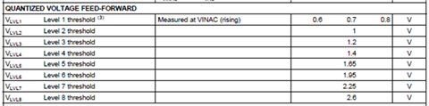
the IC needs to set the correct multiplier level using the VINAC input.

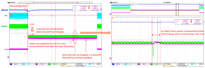
However, as shown in the waveform below, we have confirmed that the multiplier level changes when VINAC is always above 0.7V.

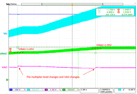
CH2_Vin , CH3_VINAC , CH4_VAO

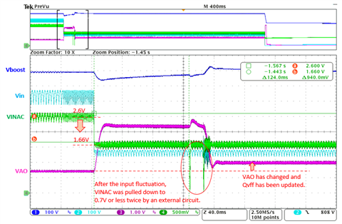
Changes in VAO occur when VINAC crosses thresholds such as 1.65V and 1.95V. Only when VINAC crosses from a low value, there is no change in VAO when changing from a high value to a low value.

I have the following question.

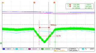
1.Does VINAC have to drop below 0.7V to update the multiplier settings?

2.Can the multiplier settings be updated without VINAC dropping below 0.7V as in the waveform above?

 If it occurs, please tell me the control sequence.

The following questions assume that the multiplier settings can be updated by dropping VINAC below 0.7V.

3.Can we set the correct multiplier level by dropping the VINAC input below 0.7V from the outside?

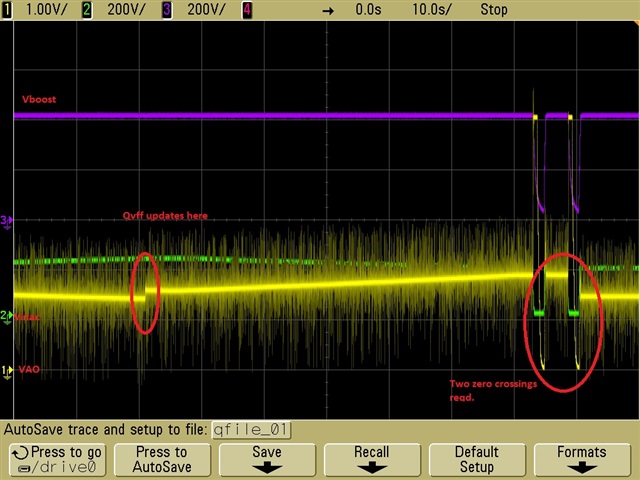
4.When VINAC drops below 0.7V, what timing input information is used to update the settings?

 For example, information about 2 seconds before dropping below 0.7V.


Best regards.

  • Hi,

    Thank you for the query on UCC28070 and sharing your observations.

    1. As these are designed for AC input voltages which you mentioned, the voltage needs to drop to less than 0.7V to update multiplier settings.
    2. Above 0.7V and for DC conditions, we have not verified the update and currently do not have sufficient data to demonstrate this behavior which you observed. However I have been trying to capture some data and feel that Qvff will update upwards without the zero crossing (but not downward). But we will have to debug this issue more and currently I do not have an EVM to debug this. We can try checking this, but it will take a couple of weeks to confirm.
    3. Yes, you can drop the VINAC below 0.7V for update. Qvff level update depends upon depends upon detecting the zero crossing level of the input voltage waveform The line voltage goes to zero every half-cycle, so the only way to detect if the line voltage peak has fallen is to use the zero-crossing as an indicator that a new cycle is coming, and to compare the next new peak to the old peak.   If the new peak is lower, then a lower Qvff level is clocked in and the multiplier gain is increased. The zero crossing detection level is 0.7V inside the controller. If your Qvff is never updated, IMO current will be affected as you suggested and current reference will be sub optimal where we will end up delivering lowering power at lower input voltages.
    4. You might have to pull the VINAC pin to ground (below 0.7V typically for 50uS) periodically to trigger the update of the QVFF table for changes in input voltage.

    Please let s know if you have additional questions.

    Regards,

    Harish

  • Hi,

    Thank you for your reply. 

    What you are feeling and what we are seeing seem to match. I understand that you don't have enough time to check. But as you say, it can be power limited at low input voltages if Qvff is unintentionally updated higher. Please reply as soon as possible to avoid this problem.

    Please let me ask you an additional question.

    As shown in the waveform below, after the input voltage fluctuates, VINAC is pulled below 0.7V with an external circuit, but Qvff does not seem to be updated. VINAC is pulled out only once after the input voltage fluctuates, but in order to update Qvff, is it necessary to pull out VINAC periodically as you answered in 4 above?

    VINAC is pulled out with the following waveform.

    I would like to update the Qvff level at the timing of extraction by an external circuit, so please let me know why it is not updated.

    Best regards.

  • Hi,

    Thank you for posting the detailed waveforms. I think the time duration for which it is pulled down is fine but I think it needs a periodic pull down of VINAC to trigger an update. Also you will need to pull it low at 50-60hz rate. I will get  UCC28070 board mid next week, when I can try testing this behaviour.

    Please let us know if you have any questions.

    Regards,

    Harish

  • Hi,

    Did you get an evaluation board for the UCC28070?

    Please test the following .

    1.Unintentional Upward Qvff Update

    2.Qvff is not updated even if VINAC is pulled below 0.7V

    Best regards.

  • Hi,

    Can you confirm the above matters?

    Please let me know if you need any information.

    Best regards.

  • Hi,

    Thank you for following up on the query. The e2e site was down on maintainance last week and saw your query only today morning. I will do the testing but will have an update only end of this week or early next week as we have a couple of official holidays this week.

    Regards,

    Harish 

  • Hi,

    I know it's time to update. I will also try to verify by pulling out VINAC multiple times. It would be helpful if you could update the information as soon as possible.

    Best regards.

  • Hi,

    I have tried pulling out the VINAC twice and confirmed that the Qvff is updated.

    From this result, it is inferred that the VINAC information used to update Qvff is the maximum value in the period between the two timings when VINAC is below 0.7V. In the waveform I posted last time, when VINAC is 2.5V, there is a pull-out of 0.7V or less, so the maximum value of VINAC between the two pull-out timings is 2.5V, and I think that even if VINAC was low, it was still set at a high level. Is this perception correct?

    Even if VINAC is not pulled below 0.7V, the Qvff level is updated in the upward direction. Regarding this matter, it is thought that it is due to the control method of the IC, so please answer whether it is correct operation.

    Best regards.

  • Hi,

    Sorry fr the late reply.

    I was able to test under DC condition and the following was the pattern of Qvff update.

    1. At startup, input voltage needs to be pulled down once and as soon as the input voltage reaches the boundary of particular range Qvff is updated as shown by the discontinuity in the VAO waveform.Increasing the input voltage to other levels (upward) does not require pulling down the Vinac signal below 0.7V.

    2. The other way around seems a bit tricky. Suppose we are in the bin between 160V to 187V and we wish to move to the bin below. In that case we need to pull the Vinac twice to zero for a Qvff update as shown in the figure below.

    Please let me know if you have additional questions.

    Thank you

    Regards,

    Harish

  • Hi,

    Thank you for your reply.

    Please answer the additional questions below.

    1. Is updating upward without disconnecting VINAC a correct operation in terms of IC design? I know that it will happen on the actual machine, but I'm worried if there are other problems related to this if the behavior is incorrect due to design.

    2. Is it correct to recognize that Qvff, which is updated by pulling out VINAC twice, is updated to the corresponding level referring to the maximum value of VINAC between the two pulling timings?

    Best regards.

  • Hi,

    Thank you for the query.

    1. The IC is ideally designed and recommended for AC line input voltage where there is periodic zero crossing to enable Qvff update. So the functionality for which it is intended is fine.

    2. For the Qvff update, suppose you are operating voltage is corresponding to bin 187-220V, now if you reduce the voltage to 160-180V bin, the Qvff will be updated to the new bin value after two zero crossings, until then it latches to the previous bin value.

    Hope it helps.

    Regards,

    Harish