This thread has been locked.

If you have a related question, please click the "Ask a related question" button in the top right corner. The newly created question will be automatically linked to this question.

BQ25713: Drive Waveform Analysis

Part Number: BQ25713

Hi Khalid,

I tested BQ25713 and found some question about driver waveform.

Test condition: VBUS 20V, VSYS 16V, VBAT 16V

Firstly, Power up from battery without DC source. And no abnormality in the circuit.

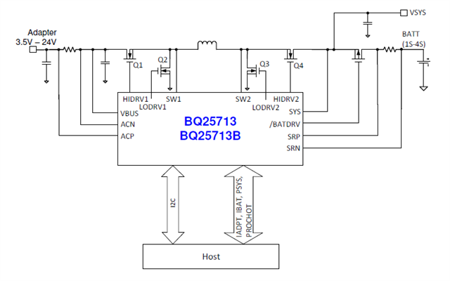
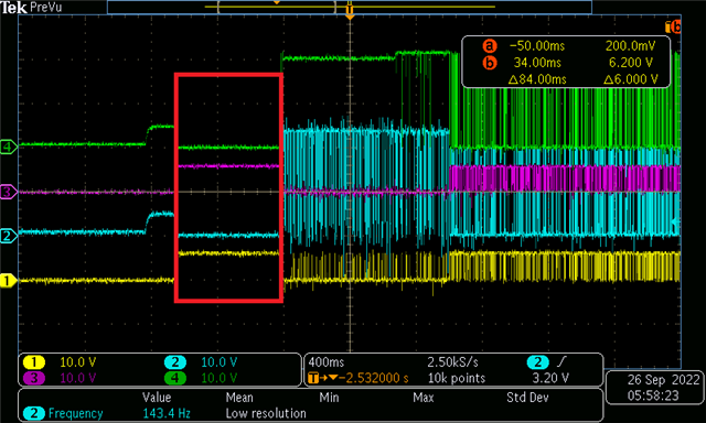
Then I plug in the adapter. VBUS=20V. The driver waveform as follows.

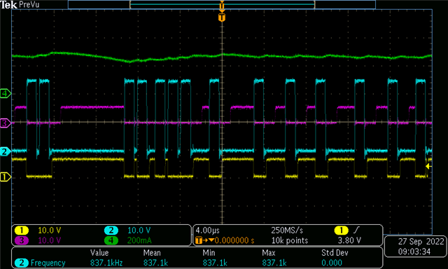
1: LODRV1  2:HODRV1   3:LODRV2  4:HODRV1

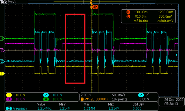
May I ask why during the period marked in the box, the two down Mosfets have to be opened? What is the effect of opening these two Mosfets? Can they be turned off via the configuration register?

Also, during charging, the same situation also occurred, what kind of operating mode is this? Is there an introduction in the datasheet? Sorry I didn't find it.

Best regards, 

Fengyu Leng

  • Hi Fengyu,

    The initial period is the VBUS qualification sequence.

    When an input source plugs in, the charger checks the input source voltage to turn on LDO and all the bias
    circuits. It sets the input current limit before the converter starts.
    The power-up sequence from DC source is as follows:
    1. 50 ms after VBUS above VVBUS_CONVEN, enable 6 V LDO and CHRG_OK goes HIGH
    2. VBUS qualification is executed 50 ms after VBUS first rises above VVBUS_UVLOZ. If VVBUS_UVLOZ < VBUS < VVBUS_CONVEN then charger fails VBUS qualification, and the charger will re-qualify VBUS every 2s.
    3. Input voltage and current limit setup
    4. Battery CELL configuration
    5. 150 ms after VBUS above VVBUS_CONVEN, converter powers up.

    I will respond tomorrow regarding the status of the LODRV1/2 during this sequence.

    Regarding the second screenshot, what is the total current load during this operation?

    Thanks,

    Khalid

  • Hi Khalid,

    I tested BQ2571XEVM, and this phenomenon occurs in the state of light load.

    VBUS=20V,VBAT=15.1V,no system load.

    When I set Charger current register below 320mA. This phenomenon is basically consistent with what the customer has measured before.

    1: LODRV1  2:HODRV1   3:LODRV2  4:IBAT

    The two down Mosfets have to be opened? What is the effect of opening these two Mosfets? Can they be turned off via the configuration register?

    Thanks a lot!

    Best regards,

    Fengyu 

  • Hi Fengyu,

    Reviewed this internally. The LO side MOSFETs are turned on during converter shut down and light load when the inductor current is zero. Doing this effectively grounds the inductor. This helps with efficiency. This can not be configured via a register.

    Thanks,

    Khalid

  • Hi Khalid,

    Thanks for your reply. 

    Could you please tell me how turning off  the LO-side MOSFETs improves efficiency?

    What could be wrong with this function?

    Best regards!

    Fengyu 

  • Hi, Fengyu,

    To study the operation of the buck-boost converter, I suggest you monitoring the inductor current and switching node waveform at the same time. 

    Regards,

    Tiger