This thread has been locked.

If you have a related question, please click the "Ask a related question" button in the top right corner. The newly created question will be automatically linked to this question.

TPS2410: Can unused the output signal pin be floating?

Part Number: TPS2410

Hi expert!

I have questions about TPS2410.

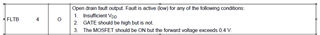
1. Can FLTB, STAT, PG be floating if unused?

2. How to deal with UV pin pin if it isn't used, short to GND or VDD?

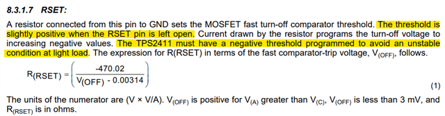
3. Can this device support about 1mV VSD reverse off threshold?

Best regards

Shuai

  • HI Shuai,

    1. PG, STAT and FLTB pins may be left Open/ Floating when unused. 

    2. OV and UV should be connected to ground when not used

    3.  Yes, using RSET, we can program the reverse turn OFF threshold to required value of 1mV using the formulae below. 

  • Hi Praven!

    Thanks for your help, customer has started evaluating of TPS2410. But they still have some specific questions.

    1. What is the humidity sensitivity grade of this device?

    2.What is the difference between TPS2410PWR and TPS2410PWRG4?

    Shuai

  • Hi Praven!

    I have a question about the logic diagram of this IC.

    ________________________________________________________

    In DS, it says Fault is active (low) for any of the following conditions:

    • Insufficient VDD

    • GATE should be high but is not.

    • The MOSFET should be ON but the forward voltage exceeds 0.4 V.

    _______________________________________________________

    There are two assumptions, which exists in normal operation.

    Assuming the voltage between GATE and A is higher than 0.75V;

    Assuming the voltage between A and C is lower than 0.4V.

    But from the logic diagram showed in below, FLTB is 0 logic in above assumption, which is constrict with 

    the description in DS.

    Could you please help to check whether the logic diagram has error?


    Best regards

    Shuai

  • Hi Shuai,

    The correct block diagram should have an inverted input OR gate as shown below. That is if any of the inputs is 0, then the output of the OR gate should be 1. If both the inputs are 1 (i.e. NO Fault condition) then the output of OR gate should be 0. 

  • Hi 

    How about another question, part number question?

    Shuai

  • Hi Shuai,

    1. There is an MSL search tool provided on ti.com. A description of the MSL can be found here.  

    2. TPS2410PWR and TPS2410PWRG4 are the same. Please refer to Product Folder