This thread has been locked.

If you have a related question, please click the "Ask a related question" button in the top right corner. The newly created question will be automatically linked to this question.

LM76005: Periodic noise on output when loaded

Part Number: LM76005

Hi,

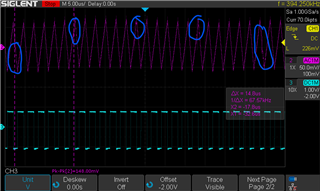
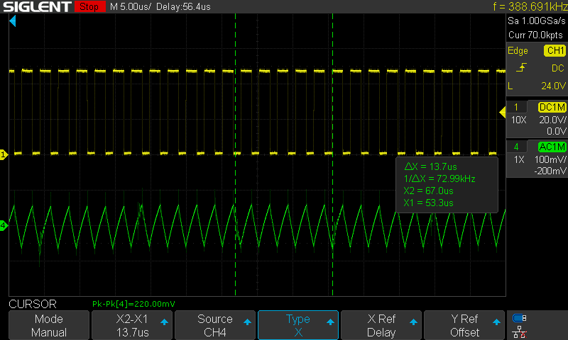
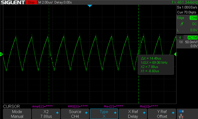
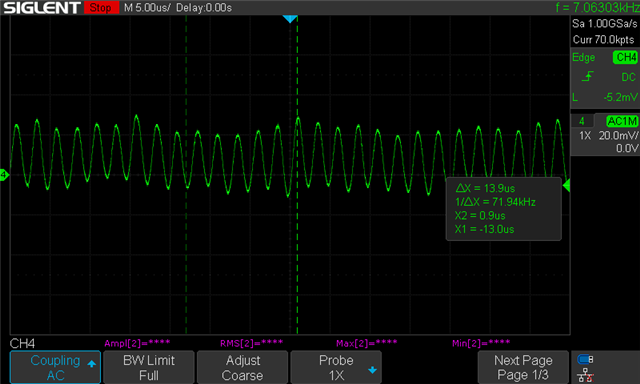
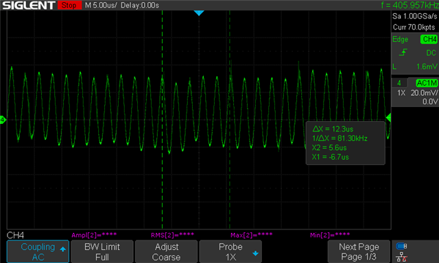
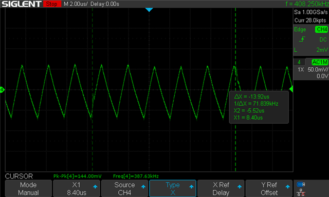
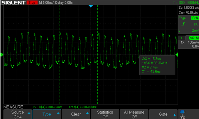
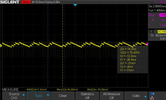
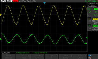
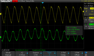
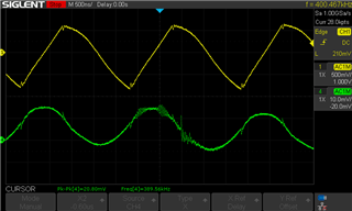
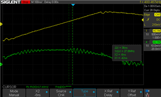
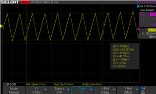
I was testing the LM76005 on a custom PCB and I noticed this periodic noise on the output when I was loading 3A. It occurs every 15us or so.

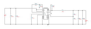
This is the circuit:

Regards,

Jerome

  • Hi Jerome,

    What was your design specs? VIN, VOUT, IOUT and FSW? What VIN does this occur?

    Is that your output voltage? It seems triangular and not sinusoidal. Is your output capacitance connected?

    Looking at your waveform the FSW is ~400kHz. The FB resistors imply ~27.7V output voltage but I'm not sure as the output capacitance is pretty large.

    You should get the SW node waveform when the issue is occurring.

    Aside from the triangularity, the waveform is periodic and does not show any instability. I would definitely check your output capacitance and if you can find it try to find an anomalous waveform of SW node that would be more useful.

    Hope this helps,

    -Orlando 

  • Hi,

    Vin = 48V, Vout = 27.7V, Iout max = 3A, Fsw = 400kHz. 

    That is the output voltage with an AC coupled oscilloscope probe. The output capacitance looks connected? I can try resoldering it perhaps.

    I will also try to get the SW node waveform.

  • Jerome,

    Are you using the exact webench bom?

    Check that your inductor saturation current is greater than the output current and LM76005 current limit (6.8A typ).

    Also check the output capacitor voltage rating.

    If you could zoom out and show the "problem" every 15us that would be more useful.

    -Orlando

  • Hi Orlando,

    I am not using the exact webench bom. The inductor saturation current is greater than 6.8A.

    The electrolytic output capacitor voltage rating is 35V but the ceramic capacitor is 100V.

    It's hard to see the noise when the waveform is zoomed about but here:

    CH1: VOUT (AC Coupled) CH2: SW Node

  • Hi Jerome,

    Ahh ok. Is that cyan curve the SW node?

    If it's DC coupled then it should be a square wave that swings from 0V to VIN. 

    Theres no reason SW should be that negative when DC coupled.

    Are your oscilloscope probes GNDed correctly?

    Check your output capacitor, for a capacitive node the output voltage should not be that "sharp" or discontinuous.

    Actually what is the output capacitor ESR? If its large then it could be that ESR causing the triangular wave.

    If your switch node is stable then the LM76005 is working as expected.

    It could be something downstream of the converter, have you tried with a resistive load?

    -Orlando

  • Hello Orlando,

    Sorry for the late reply, but I reprobed the SW node. It looks like I was probing something else on the circuit in that first shot. Here's the new scope shot:

    CH1: SW, CH4: VOUT (AC COUPLED)

    I have an electrolytic and ceramic capacitor in parallel at the output. The ceramic capacitor's ESR is 17 Ohms (DF of 0.05 at 1000kHz, 0.47uF). The electrolytic is 0.16 ohms.

    I am using an E-load to apply a constant current load of 3A.

  • Hi Jerome,

    This waveform looks good, the converter is switching fine.

    The output voltage ripple pk-pk is large, but that should not cause those glitches. (look like very high frequencies)

    The ceramic ESR is 17Ω?? That seems very high for a ceramic capacitor, is it leaded or SMT?

    I'd say try removing that capacitor or using a different ceramic. Ceramic ESR should be mΩ scale.

    Also please confirm with a resistive load. It could be the Eload control loop trying to react to the output voltage ripple.

    Hope this helps,

    -Orlando

  • Hi,

    I made a mistake, the ceramic ESR is 11mOhms.

    Here is the scope shot with a resistive load. The noise is still there:

  • I tried using the LM76005 eval board to see if I can replicate the issue.

    No load VOUT:

    3A load (E-load) VOUT:

    So the noise only occurs when the output is loaded, whereas the no load signal looks clean.

  • Hi Jerome,

    Thanks for checking the EVM in your test setup. 

    The output voltage is more "rounded" on the EVM as the output capacitors are ceramics.

    The TI EVM with the Eload is showing a small amount of the noise.

    But I don't think that its anything to do with LM76005. 

    The LM76005 can only commutate SW node to control VOUT.

    The SW node is stable and these VOUT noises are too fast for the LM76005 to notice or even respond.

    This could also be some issue with oscilloscope or scope probes. Does this happen using different probes or on a different scope?

    Hope this helps,

    -Orlando

  • Hi I tried a different scope and I still see the noise:

    One thing I did realize is that this noise is about ~70kHz which is the switching frequency of the ACDC that gives the VIN of the LM76005... I will try to filter the input a little better and perhaps that will solve the issue.

  • This is what the input ripple looks like when the output is loaded with 3A:

    This is what the input ripple looks like when there is no load at the output:

  • Hi Jerome,

    Looks like you're having some interactions between the AC/DC & the DC/DC converters.

    Is there a filter between the two converters? You may want to place a magnetic (inductor or bead) between the output of the AC/DC and the DC/DC.

    What capacitances do you have on the DC/DC input? You can try to increase that input capacitance as well as dampening that node with a capacitor with ESR, like an electrolytic.

    You should probe VIN & VOUT ripple together, as well as some control signal from the AC/DC, and try to see what is happening at that moment the VOUT ripple is noisy.

    Hope this helps,

    -Orlando

  • Hi Orlando,

    Sorry for the late reply

    1) There is no filter between two converters aside from some bulk/bypass capacitance. I can try placing a bead in between.

    2) I have a 4.7uF and 0.47uF capacitor at the DC/DC input. How does higher ESR help? I thought lower ESR is generally better for filtering.

    3) I have since been mainly debugging the evaluation board setup before I go back to debugging the custom board...
    Here is the scope shot with the LM76005 powered by a 48V power supply and loaded by an e-load at 3A CC:

    CH1: VIN (AC), CH2: VOUT (AC)

    Here is the scope shot powered by the 48V AC/DC and loaded by an e-load at 3A CC:

    With this I am somewhat more biased towards the AC/DC being the source of the noise... However, the input to the LM76005 (Output of the AC/DC) seems to be very clean... I will try adding more filtering between the AC/DC and LM76005 but if you have any more insight that would be great.

  • Hi Jerome,

    1) Yeah you can try placing a bead. 

    2) In an input filter, you want a parallel cap with ESR for damping, the LC of the filter will have a resonant frequency with very sharp Q, so you want to dampen that resonance and reduce the Q peaking. 
    See: https://www.ti.com/lit/an/snva538/snva538.pdf 

    3) The AC/DC output can be clean with no-load or specifc impedance load yeah. Switching power supplies will have an power supply input impedance that varies with frequency. See appnote above.

    Hope this helps,

    -Orlando