This thread has been locked.

If you have a related question, please click the "Ask a related question" button in the top right corner. The newly created question will be automatically linked to this question.

LM5156: flyback primary regulation tool

Part Number: LM5156
Other Parts Discussed in Thread: LM5155

Hi team,


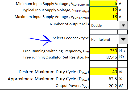
1.My customer is interested in using LM5156 as flyback in primary regulation,

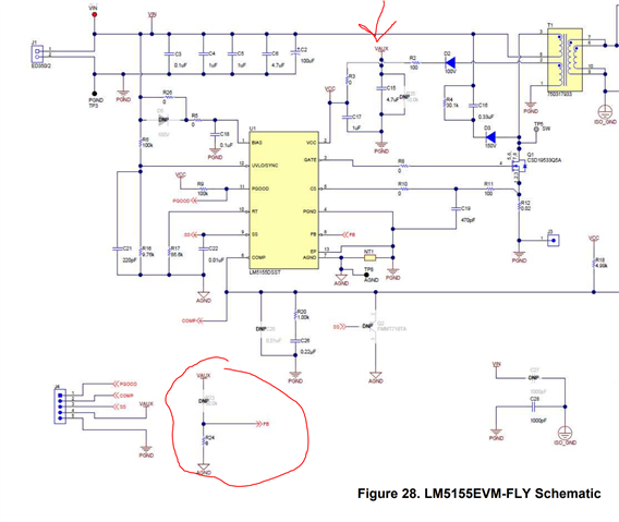
But the calculator only support secondary regulation, and I couldn’t  find more related schematic about primary regulation in the datasheet.

Would you provide any excel tool and schematic of LM5156 that can support my customer design with “primary regulation”?

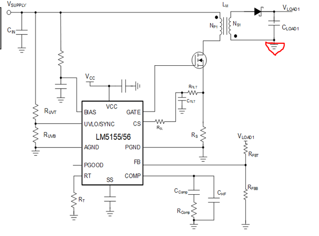
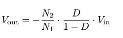
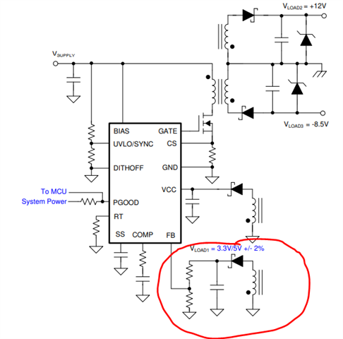
2.and another question for below picture, is the Vload1 voltage designated by turn ratio to primary side or feedback resistor  ratio like normal boost  application?


Regards,

Fred

  • Hi Fred, 

    Thanks for reaching out. In the Excel file you can select Isolated or Non-isolated in row 12.


    What are the specs for this design? In the reference design section of ti.com there might already be a ready reference design for a PSR flyback with this device (or with the LM5155). The voltage divider on the FB pin of the IC is calculated to give 1 V with respect to the voltage of the winding. 

    Kind regards,
    EM 

  • Hi EM,

    if I chose "isolated", it only shows secondary regulation. Even EVM itself is secondary regulation as well.

    so calculator doesn't have primary regulation setting, right?

    spec is below:

    Vin: 19~28V

    Vout:24V 

    Iout: 2A

    would you take an example to elaborate on FB pin setting, I didn't get it well

    for example, if turn ratio is 1: 0.5, if my Vin is 20V, then my aux winding voltage will be 10V?

    does this mean my upper and bottom resistor of FB divider should set 9:1  ?

  • Hi, 

    In this case you could choose 'non-isolated' for the PSR flyback, keeping in mind that the winding used for the feedback is on the primary side of the transformer and not on the secondary. If for example the AUX winding voltage is 10 V, you need to calculate the feedback divider with respect to having 1 V on the feedback pin, for example 5.5kOhm and 50kOhm (because 1V/5.5 *(50+5.5) = ~10V).

    The EVM can be configured as PSR flyback too: 

    Here an example of PSR Flyback  https://www.ti.com/lit/df/tidm430/tidm430.pdf 

    Kind regards,
    EM

  • HI EM,

    thanks a lot for your reply, so I just have to keep in mind that the GND below is different even though I choose "non-isolated"

    is Aux winding at primary side induced by Vin or Vout?

    I mean if my Vin ranging from 19V~28V, is that gonna change Aux winding voltage?

  • Hi Fred, 

    The AUX winding in a PSR flyback has a turns ratio calculated with respect to the primary winding (where Vin is applied). 

    Kind regards,
    EM

  • Hi EM,

    sorry

    I don't get your answer.

    for example. if primary to AUX ratio is 1:0.5.

    based on my Vin=20~28V

    does this mean the aux winding voltage could be 10V ~14V  ?

    if yes, does that mean my FB resistor has to change accordingly?

  • Hi Fred, 

    PSR means Primary Side Regulated, so the regulation happens on the AUX winding voltage where the feedback is connected. It's basically the same mechanism as if the feedback resistor is connected to the Vout. You do not need to change accordingly the FB resistors. 

    Kind regards,
    EM

  • Hi EM,

    what would happen if there's a small error between FB divide Voltage and aux winding voltage?

    for example, FB ratio is 1:9, so output should be 10V, 

    however , the aux winding is 1:0.55, so output should be 11V,

    what would happen if there's a 1V voltage difference, what will be the AUX voltage eventually?

  • Hello Fred,

    As the AUX voltage is the regulated one, this will be still at 10V, but your main output voltage will be different if the ratio is different.

    Best regards,
    Brigitte

  • Hi Brigitte,

    I thought the output voltage is decided by the ratio of primary to secondary instead of secondary to AUX .

    would you explain why secondary winding to aux winding ratio also can change output voltage?

  • Hello Fred,

    If the AUX is the regulated voltage, D is defined by AUX regulation. D influences the voltage on your output.

    Best regards,
    Brigitte

  • Hi Brigitte,

    thanks, so in the previous question, I brought up a example ,

    so if the AUX voltage will be fix at 10V by FB resistor like you said, and the "secondary" to  AUX winding ratio is 1:0.55 .

    does this mean the output will be 10x1/0.55=18.182V ?

    am I right?

    Regards,

    Fred

  • Hello Fred,

    Not that accurate, but yes in this range.

    Best regards,
    Brigitte

  • Hi Brigitte,

    got it , so maybe 18V