This thread has been locked.

If you have a related question, please click the "Ask a related question" button in the top right corner. The newly created question will be automatically linked to this question.

LMG3411R070: UVLO limits not found in datasheet

Part Number: LMG3411R070


Hi

Reading the datasheet tells us:

Page1: UVLO protection on all supply rails.

Page6: Expected output from 5V LDO and VNEG.

Page7: UVLO parameters for the12V rail.

Page13: Figure features an ULVO block that lists that it monitors +5V, VDD and VNEG.

Page14 and Page15: lists that an UVLO event will drag FAULT low.

However, I cant seem to find what voltage levels on VNEG and 5V that may cause a UVLO event. Where can they be found?

Best regards

Martin

  • Hello Martin,

    Thank you for your question. The UVLO is triggered when

    • VDD drops falls below thresholds from the data sheet 
    • or LDO5V falls below 3.8V typ.
    • or VNEG goes above -12.8V typ.

    Best Regards,

    Kyle Wolf

  • Hi

    So seeing -10.5V on VNEG after a while and with a whining coil and a FET that is getting warm ( 40degrees) without switching anything is obviously a cause for concern.

  • Hi Martin,

    The Vneg pin voltage is internally regulated by the internal buck boost.

    What is the inductor you are using for the buck-boost converter?

    Thank you,

    Kyle Wolf

  • Hi Kyle

    To be clear; This solution has worked but i have had a few products that have failed in the field.

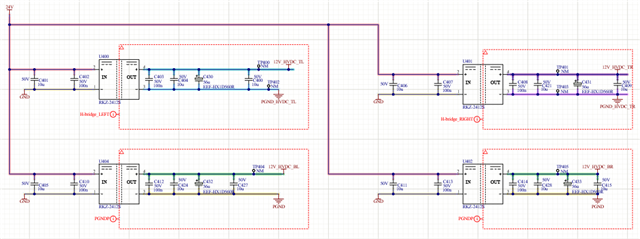
    The inductor used is BRC2518T220K as suggested from the datasheet.. Only one of the shown digital isolators are mounted. A SIP7 isolated unregulated 24 to 12 converter is used to drive each of the 4 legs of the H-bridge

    It seems like the buckbooster has failed due to how i run the bridge. 

    // Martin

  • Hey Martin,

    A few more questions regarding the scenario around the devices that failed.

    • Which inductor in the system is whining?
    • Is the failure occurring on the high side or low side device?
    • What topology are the devices being used in?

    Thank you,

    Kyle Wolf

  • Hi

    The whining comes from the BRC2518T220K. On the board in front of me, it is the BR (Bottom Right) leg of the H-bridge, so that is low side. But i have also seen it on the high side.

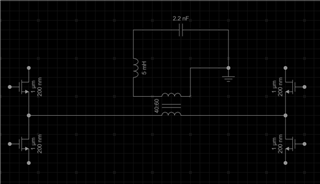
    Topology: The H-bridge is connected to a transformer with 40:60 turns. The output is connected to a lossy serial LC oscillator (the cap is intentionally lossy) where one the transformer outputs is connected to protective earth. This is an extremely simplified schematic.

    The system is then driven as a PSFB starting a a very low duty cycle 

    It there anyway that the buck boost can be broken in this way?

    Best regards

    Martin

  • Hi Martin,

    Could you try to supply a regulated 12v supply to the VDD pin on the low side FET that is showing the issue and see if the whining coil or heat increase is still observed. Once using the regulated 12v supply could you also check the voltage on the VNEG pin.

    Best Regards,

    Kyle Wolf

  • Hi Kyle and thanks for taking the time to look into this

    So I connected 12V from my lab supply and it draws 50 mA. Bare in mind that this also supplies one side of a ADuM2286CRIZ from the 5V LDO.

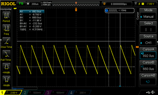
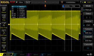
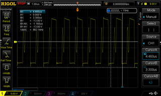
    The VNEG pin is still at -10.5V. I have also attached some scope images. First VNEG

    And then two images of the switchnode.

    Best regards

    Martin

  • Hello Martin,

    Kyle is currently out-of-office, but I have been following this thread with Kyle and can offer some suggestions for you.

    First, please send scope shots of the VDD and VNEG pins when the device is on but not switching, this can help narrow the issue more. After you take and send those measurements, assuming there is no obvious solution, my next recommendation for you would be to swap out the LMG3411 devices with new ones and retest. To retest, power up the devices with VDD without switching, and then begin switching and see if the VNEG voltage issues persist.

    This recommendation has worked in the past and will rule-out a single device issue. 

    Regards,

    Zach

  • Hi

    I can answer some of these questions without testing as i have already done them on a previous board.

    The scope pictures in my previous post are with the LMG3411 on but not switching. As /FAULT is active i am not sending pulses to the LMG3411.

    I will need to do some modifications to allow my system to switch while /fault is asserted. I can do them on Monday.

    This is the third board i have encountered this problem on a board. The last two times however, we have not time to look into it deeply and just replaced the LMG3411 directly. After that, the board worked again. To be clear, the LMG3411 has been working and then after a couple of hours, of switching this problem has occurred. I have seen it on both high and low side LMG3411 in my H-bridge. I realize that the problem might be the use case i am applying, but the way that the device appears to break with only VNEG being out of spec seems a bit strange.

    Best regards
    Martin


  • Hello,

    I would first like to understand more of the waveforms you sent, it appears that the devices are switching according to the switch node voltage. Maybe I am interpreting this incorrectly, please elaborate if you could.

    Based on your additional information, and the fact that this does not appear to be an unorthodox use case, I am lead to believe that part of the circuit is running at near peak values, or some transient event is causing the device to fail after a couple hours.

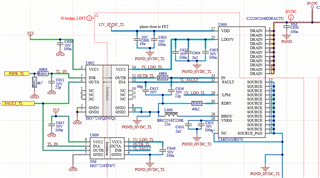
    If the VDD pin were to experience a transient event, it could easily damage the VNEG pin since the VDD voltage supplies the circuitry used to generate VNEG. Could you share more information about where the "12V_HVDC_TL" pin is coming from?

    Thanks,

    Zach

  • Hi Zach

    The device is not switching in the images scope images in previous posts. I have just applied 12VDC from a regulated bench supply and it reported that it sourced 50mA. I don't think that you are interpreting the scope images wrongly. They show VNEG and the switchnode while the IN signal is held low.

    I could share design files if you had the time to investigate this further.

    12V_HVDC_TL comes from isolated supplies as follows. One for each leg of the H-bridge

    The HVDC to PGND rail is 360VDC so there is no its not near the peak values. I myself is consider a transient event the culprit, but it is still strange that device should break in this way. I am currently hardswitching the current and i am looking into if i instead can change into softswitching.

    // Martin

  • I see now, thanks for the clarification. This problem does seem to be obscure, if you would like to share your design files I can certainly take a look and see if anything sticks out in the schematic or layout. There could be some layout problem causing noise at the VDD pin, and I will look, but want to also manage expectations as well.

    Feel free to reach out to my email (z-soviero@ti.com) and share the design files.

    Thanks,

    Zach

  • Hi Zach

    I have sent you the material.

    Best regards

    Martin