This thread has been locked.

If you have a related question, please click the "Ask a related question" button in the top right corner. The newly created question will be automatically linked to this question.

TPS65987EVM: Not able to use USB Data and Power (PD) Simultenously

Part Number: TPS65987EVM

Hi,

We are designing a product in which we will need a docking station block.

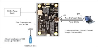
For our application, we will need Type C cable which goes into host PC and it should charge the host PC, and simultaneously we should be able to use data (For connecting a USB device). 

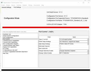
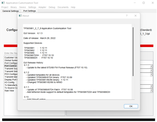
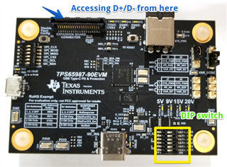
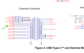
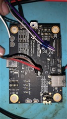
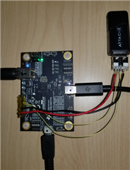
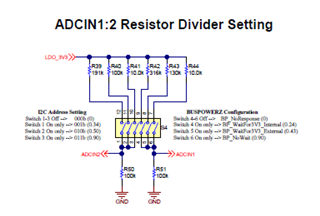
For checking this scenario, we are using TPS65987EVM.

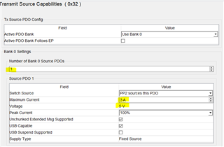
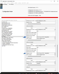
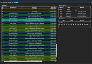
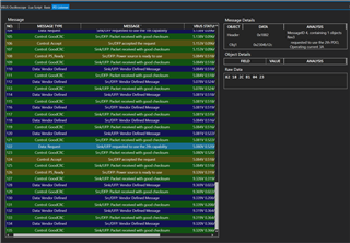
When we programmed the EVM for DFP mode only then it only charge the laptop. We cant use the USB port (As a downstream port).

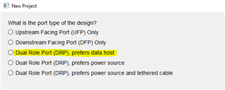
And when we programmed the EVM for DRP mode (prefers data) then we can only use the USB port(data) and no power for charging.

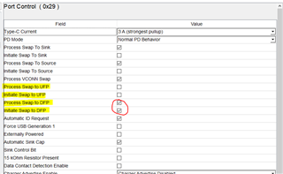
Can you please help us how to enable the Data and power modes simultaneously?

Please let me know if you did not understand our requirements properly, I can explain it in detail.

  • Hi Nikhil,

    Our EVMs are not designed to be able to actually transmit any data through its port since the SBU lines are not connected (can only simulate Data Role). 

    The TPS65987EVM should be able to be a DFP and provide power (as Source) simultaneously, check to make sure under Transmit Source Capabilities there are Source PDOs available.

    By default when you make a new project and select  DRP, prefers data host then the project will configure Port Control (0x29) to enable the PD to act as a DFP only and disable settings to allow PD to become a UFP. The project configuration should also include source capabilities (as mentioned previously). 

    If possible, can you capture a PD log to see what PD transactions are happening? 

    Thanks and Regards,

    Raymond Lin

  • Hi Raymond,

    Thanks for the reply.

    We will need the mode as you mentioned like TPS65987 should be DFP and provide power simultaneously.

    I think I am using a different version of the customization tool. The options for port control (0x29) are different for me. Please check the attachment.

    Can you please let me know what setting should I do in this version or can you send the customization tool that you are using?

    and I will share the PD log soon.

  • Hi Nikhil,

    You are using the correct version of the GUI. When you make a new project, select "Advanced" to access more registers to configure, such as Port Control (0x29) as shown in the previous thread. There you will be able to configure the PD's power and data role more effectively. 

    Thanks and Regards,

    Raymond Lin

  • Hi Raymond,

    I have created a new project with DFP- prefer data host and disbaled the process swap to DFP and initate swap to DFP option.

    I have also added the source PDO's and modified the I/O Config (0x5c) register to map the evaluation board's Buck converter for different PDO's voltages (5V- GPIO14, 9V-GPIO15,15V-GPIO17, 20V-GPIO20), So that the buck converter set the voltage according to the Sink PD device requirement.

    But still, the board is not working as data and PD simultaneously.

    I tried below different scenarios with the evaluation board:

    1. Evaluation board connected to the Laptop (Type C port) using Type C to Type C Thunderbolt cable.

       i) evaluation board work as DFP and goes into data mode. I can access a USB device connected to the evaluation board.

       ii) While data mode is active, the evaluation board doesn't charge the laptop (No PD).

       iii) In the PD logs,The evaluation board only broadcast the one 5V PD capability.

       iv) Please check the below screenshot of PD logs. 


    2. Evaluation board connected to mobile phone. (To test if PD is working)

      i) The board goes into PD delivery mode and charges the mobile phone at 9V.

      ii) PD works in this case.

      iii) Please check the below screenshot of PD logs.

      iv) In the PD log, the Evaluation board broadcast all 4 voltages PDO's capability.

    I have captured the PD logs using Power-Z PD tester. You can see the PD logs in detail using the Power-Z KT toolbox software.KT002 PC Software 20210423.zip

    Please open the attached log files in the software.Power-Z PD logs.zip

    Please check TPS65987 application customization tool project file that I used. tps65987.zip


    If possible, Can you please send me a project file of the application customization tool with the appropriate configuration so that I can import it and test it?

  • Hi Nikhil,

    I'll take a look through the PD logs and see if there's an identifiable issue. 

    Regarding the configuration, can you re-specify the power (Source Only, Sink Only, Both/DRP) and data role (UFP, DFP, Both) you would like the EVM to enumerate as well as the Source/Sink PDOs? 

    Thanks and Regards,

    Raymond Lin

  • Hi Raymond,

    Please check the below specs that we will need.

    1. EVM should acts as a power source only to charge the laptop using USB PD. Below are the required PDO's.

        5V@3A / 9V@3A / 15V@3A / 20V@3A


    2. EVM expansion port should acts as DFP (As a USB Host) to access the USB device/ USB Peripheral connected to the EVM. USB device will not be going to an audio device(accessories) so no need of SBU lines.

        EVM Type C port should act as UFP (I am not sure if the port should be UFP of DRP) so that it can connect to the laptop's type C host (DFP) port.

    3. Points 1 & 2 should work simultaneously.

    4. We don't need the Display Port mode (DP Alt mode) .

    5. EVM never going to act as Sink device. (No need of Sink PDO's).

    6. Please check the attached block diagram of the required architecture.

  • Hi Nikhil,

    Thank you for clarifying the specification, I'll attach a sample PJT by tomorrow! 

    Thanks and Regards,

    Raymond Lin

  • Hi Nikhil,

    Still working on your configuration, I'll get back to you by next Monday!

    Thanks and Regards,

    Raymond Lin

  • Hi Raymond,

    Are you able to find the proper configuration?

  • Hi Nikhil,

    Apologies for delay, please take a look at the attached PJT file based on your requirements. 

    Let me know if you have any questions or concerns!

    Thanks and Regards,
    Raymond Lin

    PJT Template: TPS65987DDH_Template.pjt

  • Hi Raymond,

    Thanks for sending the PRJ file.

    I have tested the project but only one mode is working at a time. 

    Most of the time EVM goes into PD mode and charges the laptop but not able to access the USB device.

    Sometimes it goes in the USB data mode but charging does not happen that time.

    And if I keep the PD reset button pressed on EVM then EVM goes into Data mode and once I release it, again goes into PD mode (Charges the laptop)

    Please check the attached PD logs.PD logs for updated prj.rar

    Would it be possible for you to simulate this scenario on your end?

    For connecting the USB devices to the expansion port of the EVM, I am not using the 10G-EXPANSION-EVM. I have connected the USB receptacle to the expansion port and accessed the USB D+/D- lines (Only testing on USB2.0). The USB device works fine when it goes into data mode. So is there any GPIO on the 10G-EXPANSION-EVM that might cause this problem? Or is there any role of DIP switches on the EVM?

  • Hi Nikhil,

    Let me see if I can recreate this from my end, just to clarify are you only using the D+/- lines? No VBUS, GND, or other pins connected?

    Thanks and Regards,

    Raymond Lin

  • Hi Raymond,

    I am using the VBUS (Connected to 5V test point of EVM) and GND to GND test point along with D+/D-.

    So only four wires D+,D-, VCC, GND to the USB type A receptacle.

    I referred to the TPS65987 schematic.

  • Hi Nikhil,

    Just wanted to double check, but you are using the TPS65987-90EVM from your picture above, correct? There is another EVM that is just TPS65987EVM and we want to make sure we are using the correct board.

    Thanks and Regards,

    Chris

  • Hi Chris,

    The above EVM picture is just for reference. I took it from the internet.

    I am using the TPS65987EVM. Please check the attached picture of the EVM that I am using.

  • Hi Nikhil,

    Using the EVM and the pjt file you provided, I was able to get the evm to source power and read from a usb flash drive. It seems to be working as you expected on my end. The only issue I have been having is sometimes I need to reconnect the flash drive when the computer does not find it.

    Have you made any other modifications to your board?

    Have you verified that the USB-C port on your PC can Sink power and data? Because it is working on my end, I just want to make sure any other differences in setup are accounted for.

    Thanks and Regards,

    Chris 

  • Hi Chris,

    Thanks for your efforts and that's good news, the power and data working simultaneously at your end. About the flash drive reconnect issue, I guess it's caused because of impedance mismatch of the D+/D- cable as we used separate cable instead of a differential trace. I also faced a similar kind of issue. I think it will get resolved when we design the proper PCBA for the USB port.

    I haven't made any modifications to the EVM. The only thing that is different in my setup is I am giving 5V power to the flash drive via the P5V0 test point on EVM. 

    I will check powering the flash drive via the expansion board connector as you did and let you know if its works.

    I have verified that the PC USB -C port can sink power and data. I can power and access data using Type C dock.

    Just wanted to confirm, Have you used my project or Raymond project for testing? Can you please send the project file that is working on your side? 

  • Hi Nikhil, 

    Here is the project configuration I was using. It should be the same one you sent earlier, just renamed. This is the one I was able to see the evm + flash drive working with.

    /cfs-file/__key/communityserver-discussions-components-files/196/tps65987_5F00_Nikhil_5F00_v1.pjt

    About the flash drive reconnect issue, I guess it's caused because of impedance mismatch of the D+/D- cable as we used separate cable instead of a differential trace. I also faced a similar kind of issue. I think it will get resolved when we design the proper PCBA for the USB port.

    That's good to know. When I was using the 10G-EXPANSION-EVM I did not have this issue, but the board mod with wires wasn't always working.

    I'm not sure if the 5V source matters because it is always on, but it may be worth a try.

    Thanks and Regards,

    Chris

  • Hi Chris,

    Sourcing the 5V power from the connector not worked. Sometimes EVM charges the laptop and sometimes it goes into data mode.

    Just wanted to confirm that with your setup the EVM can charge(source) the laptop and access the data simultaneously?

    Is there any role of S4 DIP switch on the EVM? Currently, all switches are in the OFF position.

    Is there any other setting in the application customization tool that I have to change? like Firmware base image. Please check the video of the programming procedure that I am following. 

  • Hi Nikhil,

    Just wanted to confirm that with your setup the EVM can charge(source) the laptop and access the data simultaneously?

    Yes, I have seen the laptop charging and accessing data simultaneously.

    Is there any role of S4 DIP switch on the EVM? Currently, all switches are in the OFF position

    You can find this info in the TPS65987D Datasheet and Design files for the TPS65987EVM.

    The first switches control the I2C Address. as long as you are able to recognize and program the board from you computer, you should not have to worry about these.

    The second half controls the dead battery mode and default configuration if boot fails. If we are booting properly, neither of these should affect performance.

    The board I have had pin 4 on and the rest off. I tested your project with all the pins off and still saw 20V Sourcing and the usb drive connecting.

    Is there any other setting in the application customization tool that I have to change? like Firmware base image. Please check the video of the programming procedure that I am following. 

    The programming looks correct. The Firmware base image is also what I have been using. Verions 707.10.10

    When you see the EVM charging the laptop, is the EVM providing the 20V contract? Originally you quoted 5V,9V,15V, and 20V contracts. When I have been running your pjt file I have been getting the 20V contract when it connects. (The 20V LED on the EVM turns on)

    5V@3A / 9V@3A / 15V@3A / 20V@3A

    Can you try loading the base DFP only configuration from the 6.1.3 GUI and see if you can get 20V charging on your laptop? 

    In the GUI:

    New Project -> TPS65987DDH -> Standard -> Downstream Facing Port

    Without changing any settings, flash the current project.

    Can you see if this configuration does a normal 20V contract?

    Thanks and Regards,

    Chris 

  • Hi Chris,

    I have tested the base DFP mode, In that EVM can provide 20V. It charges the laptop at 20V.

    And with the project that you tested, I can set EVM to 5V, 9V,15V, and 20V using PD tester. But it's not working with the laptop.

    Sometimes when I turn ON the power of EVM, it charges the laptop. Immediately after that, it goes into data mode and turns OFF the charging, and stays in data mode.

    On which machine (laptop) you tested the EVM? And which Type C to Type C cable are you using?

    I have tested it on Macbook as well but got the same result.

  • Hi Nikhil,

    And with the project that you tested, I can set EVM to 5V, 9V,15V, and 20V using PD tester.

    What do you mean by PD tester?

    On which machine (laptop) you tested the EVM? And which Type C to Type C cable are you using?

    I have an HP laptop running Windows 11. I'm not sure about the specific Type C to Type C cable, but I do not think we should need a special Type-C cable to test this.

    What kind of USB device are you using for the "Data connection"? Are you also using a flash drive or are you using something else?

    Also, can you send a PD log of the event you see below? The only thing I can think of at this point it the computer is requesting that the power role changes.

    Sometimes when I turn ON the power of EVM, it charges the laptop. Immediately after that, it goes into data mode and turns OFF the charging, and stays in data mode.

    Thanks and Regards,

    Chris

  • Hi Nikhil,

    Please note TI US will be on holiday 24th and 25th and we will be back in office on the 28th.

    Thanks and Regards,

    Raymond Lin