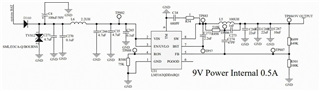
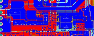
he below is LM5163QDDARQ1 schematics, please help me to review it, Now the problem is CE(Conduction Emission) issue.
The below figure is the fail .please give the suggestion to reduce the issue. 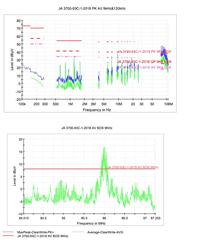
he below is LM5163QDDARQ1 schematics, please help me to review it, Now the problem is CE(Conduction Emission) issue.
The below figure is the fail .please give the suggestion to reduce the issue.