This thread has been locked.

If you have a related question, please click the "Ask a related question" button in the top right corner. The newly created question will be automatically linked to this question.

LM3488: Light load operation - how to limit current pulses?

Part Number: LM3488
Other Parts Discussed in Thread: TAS5414

Hello,

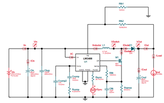
I use LM3488 as a boost converter from a car battery to 26V/3.53A output. It supplies TAS5414 audio amplifier. Its total input capacitance is 177.4uF and on the output 246uF. At the moment I am supplying it from a lab power supply which has about 0.3 Ohm resistance (inc. cables). Target appliance will have 3 meter long supply cables of AWG14.

The issue is as follows: when the power amp is disabled (default) LM3488 boost converter works with almost no load, but when it tops-up output el-caps' charge it draws current as high as 12A which causes input voltage to drop below level at which the power amp UV threshold.

I would like to limit this current. Preferably below 5A. What would you recommend?

regards

Przemysław

  • Hello Rrzemyslaw,

    Do you mean that there is too much inrush current when the converter starts because of the big output capacitance?

    As you supply it at the moment with a lab suppy: will this inrush current only happen when the battery is applied and will then the converter be always applied to the battery?

    Other than this, you can reduce the current limit, if you can buffer the load by the output capacitor.

    In addition, you can try one of the methods given in this app note: Managing Inrush Current (Rev. A) (ti.com)

    Or you use a device like LMP8646 data sheet, product information and support | TI.com

    Best regards,
    Brigitte

  • Hello Brigitte,

    thank you for your reply.

    No, I do not mean inrush current. The boost converter starts-up and afterwards repetitively tops-up already charged output el-caps to compensate for a light load. Each time it does this it draws about 12A from the input. By repetitively I mean a short group of pulses starting with the before mentioned 12A one and then about 0.8s no switching time. 

    For now I have tackled it with an extra 100nF capacitor in parallel with Rfb2. The peak top-up current dropped to an acceptable 2A, top-up time increased at the cost of the output voltage, that seems to be slightly more fluctuating under the load. 

    The device is meant to operate solely on car battery supply.

    Best regards

    Przemysław

  • Hello Przemyslaw,

    100nF feedforward cap on the feedback node seems to me a bit high. I would try to increase the crossover frequency by changing the compensation components. You could either work with load transients or bode plots to check this out.

    Best regards,
    Brigitte