This thread has been locked.

If you have a related question, please click the "Ask a related question" button in the top right corner. The newly created question will be automatically linked to this question.

BQ2000: Issues with 2 battery charge configuration

Part Number: BQ2000

Hello everyone,

I'm finding some issue on using BQ2000 while trying to charge 2 batteries Ni-Mh.

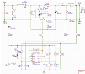
I started with the suggested schematics here below (pag.10 of the datasheet).

The only difference I use N-MOS instead of BJT for Q1, Q2 and Q3 and I added

a pull-up resistor.

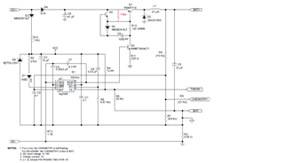
I don't use any thermistor so I changed R4 and R5 in order to be in the working range.

I made some test with 3 batteries and the circuit works fine.

I supposed to just change the ratio between R6 and R7 (the divider for the battery voltage)

in order to have the same voltage on pin4 (BATT).

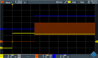
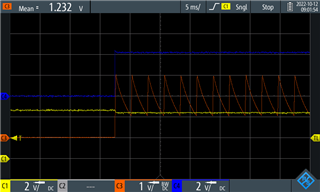
Unfortunately that doesn't seem to work. The RC pin doesn't start to work with the expected

sawtooth signal, the LED pulse around 1Hz without starting the charge.

It's like the IC is in charge qualification and doesn't proceed. But I don't see any

problem that should prevent the fast charge step. 

I have measured:

Vcc=4,5V

VBAT=1,55V

VTS=1,85V

What I'm missing?

  • Hi Suzzi,

    There might be some variations on VBAT pin voltage that make it out of range. Please refer to Eq. 3 in Page 9 of datasheet to set R6/R1 ratio. This voltage will decide charging range for given battery configs.

    Best Regards,

    Linhong

  • Hi, Linhong,

    and thanks for the suggestion.

    As I use NiMh batteries I've used, as suggested just after the Eq.3 you reffered, RB1 (N-1) times larger then RB2.

    As I use 2 cells is simply RB1=RB2.

    And in fact VBAT is already >VLBAT (0,95V) and <VMCV (2V).

    Depending on the state of charge of the batteries, I usually have VBAT between 1,1-1,5V.

    VTS too should be fine as 1,85V is between 0,25*Vcc and 0,5*Vcc (between 1.25V - 2.5V)

    I've modified the circuit using BJT transistor, so my circuit is really close to the one proposed in the datasheet.

    Now the IC has the RC oscillating and the LED turned ON but the MOD pin doesn't make any modulation

    and it's stuck at a value close to VDD.

    While powering up the charger the VDD goes up at around 4.4V (yellow signal), after a second the RC pin

    starts oscillating (red signal), but the MOD pin goes fixed around 4.2V (blue signal).

    Can you help me find the issue?

    Regards.

    Matteo

  • Hi Matteo,

    Now it seems in charging mode(LED is low). What is your battery voltage now? Make sure it is not fully charged. You may also increase your input voltage to see if MOD would change.

    Best Regards,

    Linhong

  • Hi Linhong,

    I finally realized the issue. In fact, my DC source is too low and then the MOD

    pin is always up because there's no room for the control, it's saturated.

    The fact is that using an USB as source for charging 2 Ni-Mh batteries the circuit

    can't archive more than around 300mA in output.

  • Hi Suzzi,

    Glad to hear that you have identified the root cause. Please let us know if you need any further help on charger.

    Best Regards,

    Linhong