


Hi team,
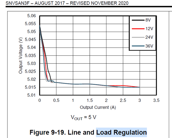
As shown in the figure, what is the reason for the increase in load and the decrease in output voltage? ( except line loss), Expect a detailed explanation. Thanks
BR
Sveinn
Hi team,
As shown in the figure, what is the reason for the increase in load and the decrease in output voltage? ( except line loss), Expect a detailed explanation. Thanks
BR
Sveinn
