This thread has been locked.

If you have a related question, please click the "Ask a related question" button in the top right corner. The newly created question will be automatically linked to this question.

UCC27712EVM-287: Ringing ON High-Side and Low-Side Gates

Part Number: UCC27712EVM-287

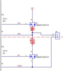
I have an application that I need to switch that needs to switch 110VDC. Right now, I am using the development kit per section 5 of the User Guide but I am not getting the same results as seen in Figure 2 and 3. I am seeing some ringing on My High Side (Channel 1 - Yellow) and Low Side (Channel 3- Blue). My output signal unloaded (Channel 2 - Pink) seems to be working as desired. I am noting the FETs are getting warm to the touch as well, and I'm concerned they are turning on when they should be off causing this. Is there something I am missing that would stop the ringing from occurring? As the HV-GND power supply is increased it get worse, see the images below. 
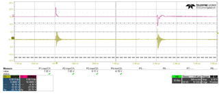
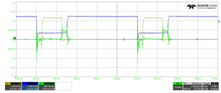
40VDC at HV and GND

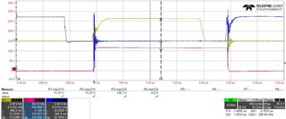
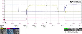
110VDC at HV and GND

  • Hi James, 

    Thank you for your question. Could you please indicate the name of the test point/jumper in the EVM that you used to probe these 3 signals?

    Best regards,

    Leslie 

  • I am using the same test points as section 4.3.5 calls out. The channel of the probes are different, but my initial post calls out the which one is which. 

  • This might be helpful as well... 

    I lifted the source pin on the high side FET, added a 10mOhm resistor inline, lifted the drain of the low side switch, and added a 10mOhm resistor inline. I then used differential probes to measure across the 10mohm resistors to see if there was a voltage drop across them to determine if I was getting shoot through. The screen shoot below shows that both resistors see a voltage drop across them, I am assuming this is when the FETs are turning on. Channel 1 (yellow) is the high side FET and Channel 2 is the low side FET. 

  • Hi James, 

    Thank you for the additional information. One thing I noticed is that the plots you are referencing in the EVM user's manual use a bandwidth setting of 20MHz for both GH-HS and GL-VSS signals and this could be the reason you are seeing more noise than what's observed in the user guide's plots. 

    Also, when measuring using regular probe tips, there's usually more noise coupling, and it's hard to differential between real transients in the system and noise introduced by the probes. I recommend to use tip and barrel method to see if the transients are real or if they are being caused by the measuring method. For example, for the GL-GND signal, you can measure at these vias:


    If you are still seeing the high noise coupling into GL-VSS after trying that, here are some additional debugging steps to try:

    • If you have a 2nd EVM in hand, it would be good to check if the same noise is observed 
    • Do you see any noise on GL, GH when HV is off or 0V?
    • Do the VCC and HV currents look as expected? The expected values are listed in the EVM user's guide, section 5.1 Power Up

    Best regards,

    Leslie

  • I do have a 2nd EVM, and both show the same results.

    Below is a screen shot with HV is off. The green channel is the HV to GND line using the tip and barrel method mentioned above. The Yellow channel is GH to HV with a differential probe and the blue channel is GL to GND with an normal probe. 

  • Hi James,

    Just to be sure, this graph is with a 20 MHz bandwidth and the tip-and-barrel measurement method?

    Best regards,
    Ethan Galloway

  • Only the HV to Gnd Line is the tip-and-barrel measurement. All but the yellow (GH to HV) channel is at 350MHz. The yellow channel is at  200MHz.   

  • To make your graphs look like those of the EVM User's Guide, can you set the channel bandwidth to 20 MHz?