KEEP UPDATING...
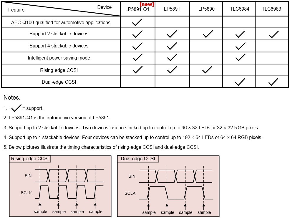
[Q1]: What are the main differences between LP5891-Q1 / LP5891 / LP5890 / TLC6984 / TLC6983?
[Q2]: How to quickly light up a LED panel with LP589x / TLC698x? Where is the sample code?
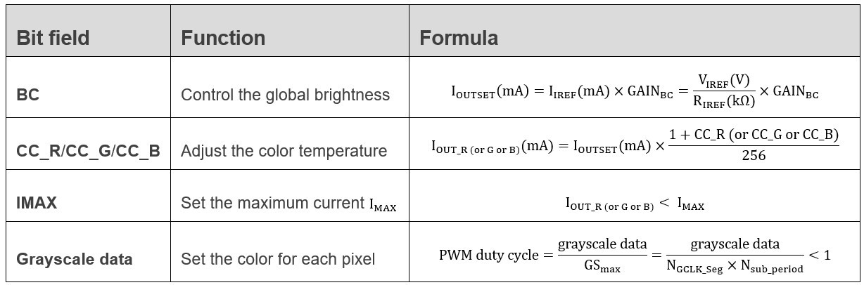
[Q3]: How to configure the color / brightness / color temperature?
[Q4]: How to implement CCSI? Is CCSI compatible with SPI?
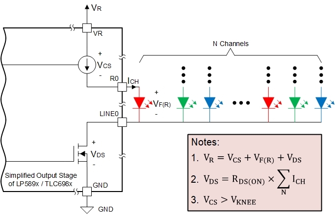
[Q5]: How to select power supplies VR, VG, VB and VCC?
[Q6]: Could you provide more relevant resources for LP589x / TLC698x?