This thread has been locked.

If you have a related question, please click the "Ask a related question" button in the top right corner. The newly created question will be automatically linked to this question.

UCD90320: Closed loop margining question

Part Number: UCD90320
Other Parts Discussed in Thread: TPS568215

1. Can you provide voltage regulator output waveform when marginning is enable (high or low)

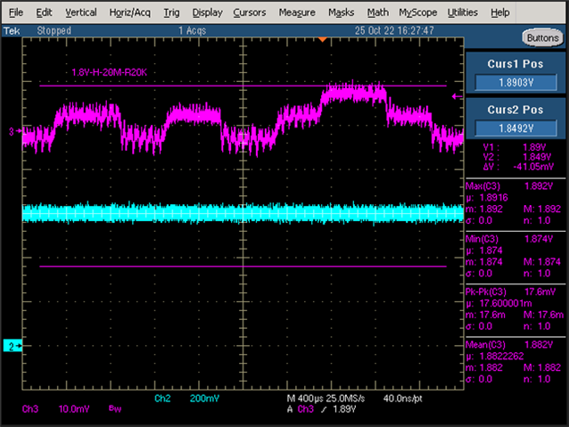
2. Following is what I captured for 1.2V output waveform with 1.2V offset when margining is enable high. Is it normal to have many spikes (overshoot and undershoot)?

3. 1.2V has also fed back to Amon pin,Is there any way to calibrate or offset for Amon pin?

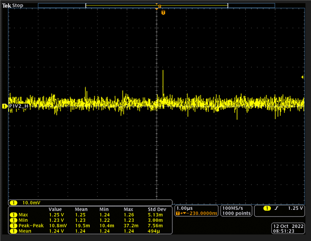
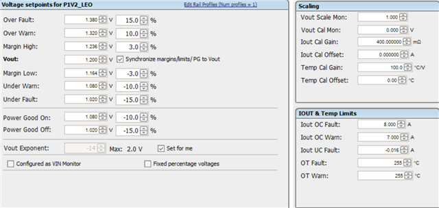
4. As shown in second photo below I have set  +/- 3% margin high and low for 1.2V  ( range 1.236V ~ 1.164V). However you can see actual measurement is over spec  (1.25V > 1.236V).

It does not seems right, Can you explain why 1.2V margin high is over +3%? 

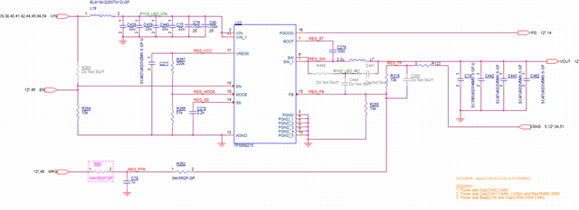
PS. Power rail 1.2V schematic is attached with margining circuit

Mike Hsu

  • Hi

    Do you have a UCD90320 EVM? it have the margining circuity to see the waveform.

    You R3/R4 and C1 number does not seem right. Have you try the margining design tool https://www.ti.com/lit/zip/slvc676 

    Here is what i got based on your design. Please check to ensure that you have the right settings.

    Regards

    Yihe

  • Hi Yihi 

    1) I have re-calcuated margin desgin according to the schematic above R90 / C78 / R262 = 84.5K ohm + 1nF +  84.5K ohm and DPWM frequency (200KHz) shown below. Please check my excel file and give some suggestion? 

    PS. these resistance, capacitance and DPWM values are given by the customer.

    2) If I have use resistors value that is smaller than R3_R4_calc. Vout_min_calc will not within Margin Low threshold, why ?

    3) For four-corner testing, Does TI recommand just look at DC level of the margining voltage or the ripple voltage should take count as well? I am asking this is because if we consider ripple voltage it may over the margin high / low threshold.

    UCD90xxx Margining Circuit Design Tool 1.2V 20221013.xlsx

    Mike hsu

  • HI

    As long as Vout_min_cal is low that your desired Margin low threshold is good, it means that it can be further lower

    As for the four corner test, it is up to your system requirement, each customer may be different.

    Regards

    Yihe

  • Question# 1, how to reduce ripple voltage in the output of the voltage regulator when margining is enable?

    Question# 2, After actual measurement, if margin high and margin low is over what I set in the voltage setpoints.  How do I reduce the voltage so it's within the range?

  • Hi

    You can reduce the frequency to improve the ripple or increase C1. 

    Try to increase the R3 and R4 so that the range is small

    Regards

    Yihe

  • Q1. By increasing the value of C1, Vout overshoot will increase at end of soft start ramp. How is it possible overshoot increase and ripple voltage decrease?

    Q2. Overshoot happens every PWM pulse or it is just first time the voltage regulator initial? 

    Q3. Can value of R3 differ than R4?

  • Hi

    Increase the C1, the ripple shall be reduced.  

    please check below to see what you observation. 

    R3 can be different wit hR4.

    Regards

    Yihe

  • In addition to question #2, I have choosen the R3/R4 value according to the excel. They are smaller than the calculated values (wider range). According to slv845a, the smaller resistor values increase Vout.

    R3/R4 are the max and min allowable Vout. The regulated of Vout_high and Vout_low should follow margin high and margin low in the voltage setpoints in the fusion digial designer tool. Howewer actual measurement of margin margin low are out of the voltage setpoints. Can you explain why? 

  • Hi

    The smaller Re/R4, the larger margining range. if the margining range is over what you expect, please increase the R3/R4

    Regards

    Yihe

  • Hi

    We prefer not to change to larger value of R3/R4 (smaller margin range) due to the tolerance of R3 and R4 and Amon pins.  I have another idea if margin low is out of the setpoints for example - 5%. Can I change to -4.5% instead? Or you have other suggestion? 

    Thanks

    Mike Hsu

  • Hi

    That's what I recommended in the another post to reduce the margin low threshold.

    Regards

    Yihe

  • I have choosen R3 and R4 that are a bit smaller than calcuated values for the margin cirucit and it works fine . However If R3 and R4 value are too small (wider range),

    Vout of TPS568215 became unstable after margining is enable. see picture below.  My question why smaller value of R3 and R4 can cause output

    unsable, but bigger values are okay? For example, 51K ohm is the calcuated value, 43K ohm fail but 49.9K ohm OK.

    As you see CH2 FB pin keeps 0.6V, however output became unstable (overshoot?)

    CH3: 1.8V output 

    CH2. FB pin of TPS568215 (0.6V)

    Mike Hsu

  • Hi

    The internal PWM adjust is about 500us(2K). it seems that the small registers or large range cause the power supply unstable.

    Please let's check and get back to you.

    Regards

    Yihe 

  • hi 

    1. I want to know why smaller range does not cause the power supply unstable if  DPWM adjust itself once every 500uS?

    2. According to slva845a.pdf, reducing DPM frequency can also minimize the voltage fluctuation, right?

    3. Unstable output waveform shown above does not happen every time, It seems happening randomly, you have to set the scope in trigger mode and wait it to happen.

        Could you exaplain why it does not happen every 500uS?

    I am looking forword your feedback ASAP

    Mike Hsu

  • Hi Mike,

    I understood your issue is with the resistances network between the VFB pin and Margining PWM. The resistors value depends also on the voltage divider resistors of the DC/DC.

    Design Voltage Margining Circuit for UCD90xxx Power Sequencer and System Manager (Rev. A) (ti.com)

    When you do your calculation if you change the PWM resistors you need to change the voltage divider resistors accordingly. Please check the app note page 2 and 3.

    Regards, Mahmoud