This thread has been locked.

If you have a related question, please click the "Ask a related question" button in the top right corner. The newly created question will be automatically linked to this question.

TPS65987D: Display made auto entry only works with specific cables

Part Number: TPS65987D

Hi Everyone,

I am looking for help, as I am currently stumped trying to solve an issue of mine. I'll try and explain the issue to the best of my ability.

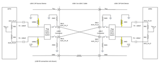
Overview: I'm currently using the TPS65987D as UFP sink device which is effectivity a USB-C to HDMI adapter, nothing too fancy. IE a USB bus powered device and the USB-C-DP converter to HDMI. The device we're using for the USB alt mode conversion is the MCDP5200 device, which we have implemented on another design without any issue and currently sell the unit with a Lindy 1m USB 3.2 COTS cable. The schematic is identical between these two designs, with the only difference being. the new one is bus powered, IE through the TPS65987D. I mentioned the previous design purely because we know it works as intended. so, you can plug your laptop into the unit with the Lindy cable and within seconds an image pops up on the display - perfect.

However, now we've implemented this circuity on the bus powered device, you would expect everything will work as before. but it does not... well kind of work, hence this question. 

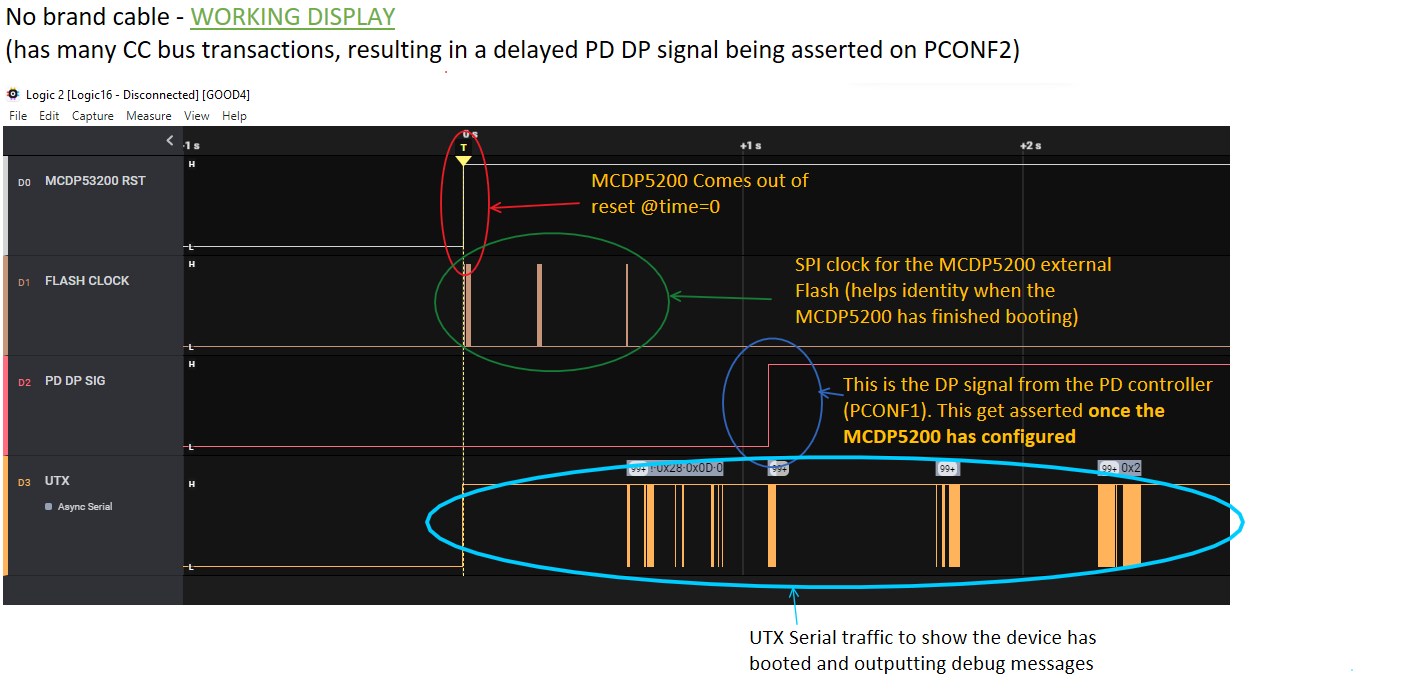
The issue we're seeing is between two cables. where one cable will work as expect and the other does not. The one which doesn't work; you guessed it; is the Lindy cable I've mentioned before. Using a no brand cable. the new unit works as expected -plug it in and boom, within seconds we get a display out of the device. However, using the Lindy cable, which we know support the data rates and power - does not produce a display nor does it auto enter into the alt mod DP type. To be clear - the only thing changing between these tests are the cable. The hardware is consistent between tests, so to the firmware and laptop which is generating the display.

We have investigated: Power supply stability, POR circuit and software for all connected devices and everything checks out. So, I'm struggling to point the finger at the hardware right now, but I could have missed something.

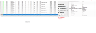
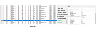
Given the only variable changing between the test is the cable; one works and the other does not; which confused me, and the known good cable doesn't produce an image. We do have access to Cypress EZ-PD analyzer, where we have observed that traffic between the laptop and hardware is different between the two cables, but this is the point where my experience of CC traffic is limited and I'm here asking for help! 

I have attached the two CC traffic files to this post, and I hope someone could shed some light onto the difference and point me in a direction to solve this issue. we've been looking at this issue for a while now without any real direction. I hope this is just a configuration issue on the TPS65987D device but I'm struggling to know which register to change.

 GoodCable.csvBadCable_Lindy.csv

Any help is appreciated!

Kind Regards Pete

  • Hi Pete,

    Thanks for reaching out to E2E!

    Let me reach out to a team member internally who may know more about how cables may affect the PD contracts. I'll try to get back to you by next week.

    Thanks and Regards,

    Chris Lim

  • Cheers Chris, I will appreciate any help on this matter - I'm stumped! 

  • Hi Pete,

    Could you send the PD log files that cypress generates? (.ccgx3 format) These will be easier to decode on our end.

    Thanks and Regards,

    Chris

  • Chris, 

    I've preformed the two cable tests again, to get this information, as I had only exported the output to CSV rather than saving it in the format you requested. the outcome is still the same; one cables work and other does not. I'll also attached the Project file too, as that might help shed some light on the matters.

    USB_C_PD_AutoEntry.zip

    Thanks in advance!

  • Thanks Pete, I'll talk to an expert on the team tomorrow and try to get back to you by COB.

    Thanks and Regards,

    Chris

  • Hi Pete,

    Sorry about the delays, the expert has been out of office for the past few days. He plans on being back in tomorrow or Friday so I will try to get back to you by the end of the week.

    Thanks and Regards,
    Chris

  • Hi Pete,

    Thanks for being patient, I talked with a team member and this is what we found.

    From the logs you provided, the main difference that concerned us was the missing ATTENTION message after the DP_CONFIGURE messages. The ATTENTION message is what passes the Hot plug detect(HPD) signal and is what Display Port uses to know when a new DP device is connected. You are not getting any display due to this message missing.

    Bad Cable

    Good Cable

    We think the issue with the Lindy cable could be related to missing SBU lines. USB-C in DP mode uses the SBU lines to to detect a device. If no device is detected, the monitor will go to sleep and there will be no display. We think that once some of the USB-C DP messages are sent, it checks the SBU line for a device and doesn't see anything, so never sends the ATTENTION message.

    Our confusion here is that you mentioned that you had this Lindy Cable working previously. Could you provide a PD log of the lindy cable working properly. We want to take a look and see if there are any differences there that may indicate otherwise.

    Thanks and Regards,

    Chris

  • Chris,

    Thank you for the insight and the pointers on where to look.

    I have attached the file which captures the CC traffic from the bad Lindy cable with the previous working product. like I've mentioned before this cable doesn't work the new product but does work on the previous model. The I've file attached shows a valid display and works as expected. I would be interested to know if you can discover anything with the new file.

    Kind regards Pete

     BadCable_Lindy-Working-DifferentProduct.zip

  • Hi Pete,

    Thanks for providing the PD log of the cable working. I looked it over with the expert and everything looks good from the Display Port routine. Unfortunately, we are running out of ideas for what could be causing your issue.

    Something you can try checking is to see if an HPD signal generates the Attention message with the Lindy Cable.

    One last thing we can check is the project (.pjt) file that contains the TPS65987D configuration, but the fact that you have the system working with another cable makes us think that we won't find the issue there. Could you still send over the .pjt file so we can take a look just in case.

    Thanks and Regards,

    Chris Lim

  • Chris,

    Me too, me too. Its ones of those problems which has stumped us too.

    Are you suggesting we trick the system in thinking the HPD on GPIO3 is asserted, to see if we get the attention message come through the CC traffic?

    I have attached the Project file too - maybe you could find something there in the setup? 

    My current thought process is leaning toward a timing attribute on the power up of the card, which we're marginal too. As this setup is bus powered, rather than "wall" powered like the previous product; could we be seeing a timing issue where the PD controller will be the first to boot up and configure but the system could be still starting or booting. in this instance could we hold off or resend the alt mode data through the CC lines? going out on a limb here.  

    Thank you for the suppoort,

    Kind Regards Pete MirrorMode_Config_C.pjt

  • Hi Pete,

    Are you suggesting we trick the system in thinking the HPD on GPIO3 is asserted, to see if we get the attention message come through the CC traffic?

    Yes, exactly that. For the attention signal to be sent, the HPD signal must be asserted into the PD controller, and then the PD controller must generate the attention message. Since the attention message is missing, we wanted to see if it is the PD controller not sending the message or possibly something else. 

    My current thought process is leaning toward a timing attribute on the power up of the card, which we're marginal too. As this setup is bus powered, rather than "wall" powered like the previous product; could we be seeing a timing issue where the PD controller will be the first to boot up and configure but the system could be still starting or booting. in this instance could we hold off or resend the alt mode data through the CC lines? going out on a limb here.  

    Maybe, it does look like a 5V PDO is confirmed and supplied before any of the Display port messages are sent, so that seems to be working properly.

    What device are you using? DH, DJ, DK

    Thanks and Regards,
    Chris

  • Hi Chris,

    Unfortunately, I cannot force GPIO3 HPD high as the display controller driving this signal has a totem pole output and forcing it high will cause excess current flow. additionally, we do not have a method of disconnecting the display controller, as the HPD signal runs within the PCB with no series elements we could remove.

    Thankfully the manufacture of the display controller is going to do us a build of software which sets HPD permanently high for the purpose of these tests. I shall report back once I've been able to test this.

    We are currently using device: DH. 

    Thank in advance Chris

    Kind Regards Pete

  • Hi Pete,

    Could you try measuring the HPD signal during the bad Lindy cable connection. I'm interested in seeing if the HPD signal goes high at all during the connection event. This way, we might not need to drive the signal externally.

    Thanks and Regards,
    Chris

  • Hey Chris,

    Some good news - we've managed to find out the issue and resolve it with the help of the manufacture for the display controller (MCDP5200). For anyone else who might have a similar issue; our issues were attributed to the "DP event signal" from the DP controller setting its state earlier or later depending on the amount of CC traffic we were getting, between different cables. This results in a change of time in the DP event signal being asserted, which could be before or after the display controller had time to finish booting and loading its firmware upon power up. We managed to get some evidence to prove the MCDP5200 was looking for an edge of a signal, rather than the absolute value of the signal at power up. which makes sense; in normal operation you shouldn't need to poll this signal to assess whether to connect the display or not. The manufacture of the part was super helpful and understood the issue and sent us an updated firmware to check the state of this signal upon power up and then swap back to edge triggering on the IO signals once booted - this worked perfectly and fixed our issues. we did have two other non-ideal solutions to the issue, like holding off the DP alt mode configuration on powerup or implement some conditional checking with our on-board processor to toggle the DP Event signal pin in the event the MCDP5200 has missed it the signal. thankfully the new firmware helped!

    Here is what it looked like: 

    Lindy cable - NO DISPLAY

    (Lindy cable has few CC bus transactions, resulting in an early PD DP signal being asserted on PCONF2 before the MCDP5200 has booted)

    We're still unsure why the CC traffic is greatly different between the two cables but given the amount of different cable and DFP configurations that are possible. the amount of CC traffic could change widely. So, implementing this firmware fix makes the whole system more robust. 
    lastly, I would like to thank the support from you and the of the manufacture in solving these issues! it was a hard find for us to find and without the combination of both, we would be still head scratching!
    Thanks, Pete
  • Hi Pete,

    Glad you were able to figure out your problem and find a solution!

    Thanks for writing up these notes on your issue and solution in case others see similar issues.

    Thanks,

    Chris