This thread has been locked.

If you have a related question, please click the "Ask a related question" button in the top right corner. The newly created question will be automatically linked to this question.

LM5060: Ringing issues and how to solve them.

Part Number: LM5060

Hello, I am using the LM5060. I have had similar issues with the evaluation module and my own prototype. 

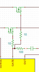
First i modified the evaluation module to resemble this:

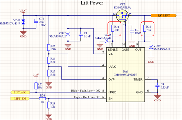
The issue i had is my load is very capacitive in nature and can generate inrush of upto 90A without including any dv/dt slow down as shown here:

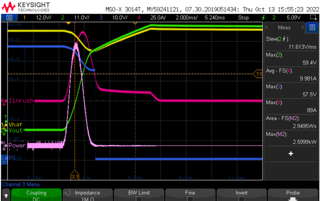
Note: The yellow waveform droops in the beginning because it is powered from PSU which hits power limit at that level and reduces voltage alittle bit. For the purpose of this investigation lets ignore it for now.

As it is, the FETs are very close/slightly over it's SOA limits and so i added 4700pF capacitor for C3.
However when i did this there was a lot of ringing added into the system (although you can see inrush is reduced). 

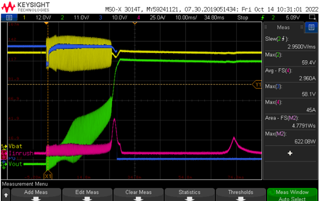
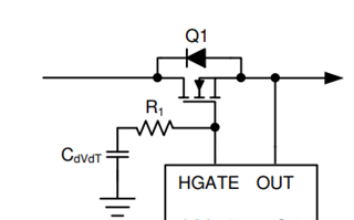
I suspected this was because of LC resonance forming on the gate line because of the added capacitance. 

I added a 2.2k resistor on the line to damp this (without concern for slow turn on because the chip has constant current source). I also added a diode for reverse direction like this: 

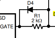
However this simply made my circuit fail instantly with the FET shorted from drain to source. 

Could you help me debug this? Note adding a parallel mosfet which i need for continuous operation creates a similar issue for ringing. 

  • Hi Nasir,

    Thanks for reaching out!

    We will check and get back on this by early next week.

    Best Regards,

    Rakesh

  • Hi Hassan,

    To resolve the ringing issue during startup, I would recommend you to add the following components in your circuit to help dampen the oscillations between parasitic L and C in the gate path. 

    • 10Ω resistance  in the gate path of each Mosfet and 
    • add 100Ω resistance  in  series with the dvdt capacitor (C3 in your circuit). 

  • Hi Praveen, i will test the following and report back. Considering there is a constant current source on the driver chip (so i should not be slowing down the switching cycle of the FET), would the 2k resistor coupled with the diode not have achieved a similar affect on dampening the oscillations? 

  • Hi Nasir,

    For damping the oscillations,  resistance value as high as 2kΩ is not required. Also, there has to be resistance in the gate path of each FET so that the oscillations caused by the parasitic oscillations between the gate's of both the FETs are also damped.  

  • Hi Praveen. The solution suggested worked really well and managed to get rid of the ringing. Very much appreciated. On a similar note i had a different question.  Considering we have a load which will be on when the hotswap is turned on, and it's very highly capacitive in nature, the given controller is not perfectly suitable. With the FETS we have, we just about manage to keep it within the SOA region and for a more robust design with the given controller would need more expensive planar FETs (which usually have high rds on and therefore we would need multiple in parallel as our continuous load is a lot as well). 
    Are there any hotswap controllers (with reasonable stock) which you could recommend? Ideally one which controls the power limit or allows some form of pre-charge. Thanks

  • Hi Hassan,

    Good to know the circuit suggested resolved your issue. Will get back to you by tomorrow on your remaining questions. 

  • Hi Hassan,

    Have you considered using dvdt (R and C from Gate to GND) circuit ? dvdt circuit will help limit the inrush current during startup and will ultimately help you to startup/charge the output capacitance while being within FET SOA.

    In case you want pre-charge feature please have a look at our latest device TPS48111-Q1