Because of the holidays, TI E2E™ design support forum responses will be delayed from Dec. 25 through Jan. 2. Thank you for your patience.

This thread has been locked.

If you have a related question, please click the "Ask a related question" button in the top right corner. The newly created question will be automatically linked to this question.

TPS1HB08-Q1: current path during turning off inductive load

Part Number: TPS1HB08-Q1

Hi Expert,

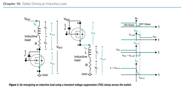
When turning off inductive load, the will trigger VBB to VOUT Clamp. But what's the principle of the clamp? Just in TVS? I see on app note it's a TVS between Vbat and Gate as below. If such, how does the current flow when clamp? The TVS is not connected directly between VBB and VOUT, then how does it clamp the voltage? 

As for VBB clamp, is it the same that a TVS is used? Then what's the current it can endure? Thanks.
BR,

Elec Cheng

  • Hi Elec,

    The clamp is between VGD. During OFF state, the gate voltage is pulled to the Source voltage. When the Drain voltage keeps rising, the VGS clamp will engage, and gate voltage will be pulled up (away from the source) to the VBAT-VCLMAP. Once VGS exceeds the Vth, the MOSFET is turned ON to clamp the Source voltage by the VGD clamp voltage.

    There's no VBB clamp implemented here. User would need to have own VBB clamp for surge etc.

    Regards,

    Yichi

  • Hi Yichi,

    Sorry that I don't understand your explanation clearly.

    The clamp is between VGD. During OFF state, the gate voltage is pulled to the Source voltage

    I understand that we need pull gate voltage equal to source voltage. But when source voltage decreases, will gate voltage decrease also? Do they tie together?

    When the Drain voltage keeps rising

    Why the Drain voltage keep rising? When turning off inductive load, there should be a large negative voltage on the source pin. 

    Thanks for your patience.

    BR,

    Elec Cheng

  • Hi Elec,

    Yes the Source and Gate are tied together with a resistor. As the Gate to Drain clamp is a stronger pull-up, once the clamp engages with the Source voltage becomes negative, the Gate voltage will be different than the Source voltage.

    As for the Drain voltage keeps rising, it's equivalent to the Source voltage keeps decreasing. It's the equivalent as you looking from a VDS perspective. Please let me know if you have additional questions.

    Regards,

    Yichi

  • Hi Yichi,

    No further question. Thanks.

    BR,

    Elec Cheng