This thread has been locked.

If you have a related question, please click the "Ask a related question" button in the top right corner. The newly created question will be automatically linked to this question.

LM5157: Schematic Review

Part Number: LM5157
Other Parts Discussed in Thread: LM5158, LM5156,

Hi team, I've got a schematic review from the customer. They want to get confirmed of their R,L,C value if they use LM5157x, not LM5158(it's on the schematic but please think it LM5157x). Also, I'd like to address that the link in LM5157x-Q1 to the quick caculation excel sheet is not working . 

Customer Specification

  1. Vin = 5V/3A
  2. Vout = +27V / -20V
  3. Application : LiDAR Sensor


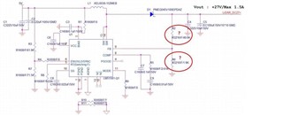
+27V Schematic


-20V Schematic
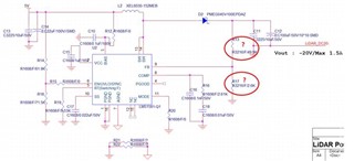


  1. Please check R2 and R6 values to make +27V / -20V output respectively
  2. 5V GND(input) and 27V GND(output) should be separated?
  3. AGND and PGND can be tied as the schematic?
  4. Please review the R, L, C values for stated in/out voltages for both +27V and -20V output
  5. To adjust Vout value, potentiometer can be used to the R6?

Thank you!

  • Hello, 

    Thanks for reaching out. The quick start calculator is published on the product folder of the device: https://www.ti.com/lit/zip/snvr511 . The schematics reports that the maximum load current is 1.5A, the LM5157 cannot deliver such load at 5V input voltage as its switch current limit will be exceeded. The feedback divider is calculated with respect to a 1V reference: 1/1.9*(1.9+49.9)~ 27.2 V. As a negative rails is needed we might suggest using a flyback that can provide both rails and using a controller like the LM5156. Let us know if there are further questions.  

    Kind regards,
    EM