This thread has been locked.

If you have a related question, please click the "Ask a related question" button in the top right corner. The newly created question will be automatically linked to this question.

TPS65313-Q1: Reset issue

Part Number: TPS65313-Q1

Hello team,

My customer occurred the DSP reset issue while using TPS65313.

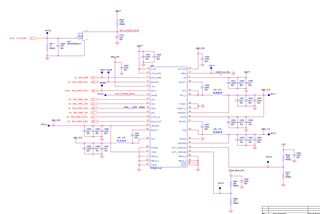
They use one simplified board (Only DSP+TPS65313 and motor driver), the SCH is as below:

Add some notes,

The connection between pin7 and DSP is cut off.

Pin 8 connect to DSP, but DSP doesn't use this function. 

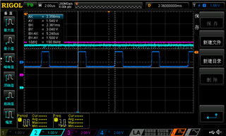
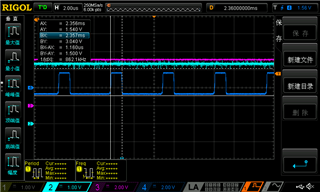
Has already masked the SCK/SDO/SDI output, only use NCS. Operate the SPI with a cycle of about 7us, that is, only the NCS signal of the SPI is switching, and the power restart will occur.

Now they don't configure PMIC, just use the default configuration. And DSP only send one SPI command 0x07 to the PMIC, and read the data from PMIC.

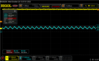
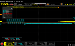
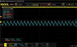
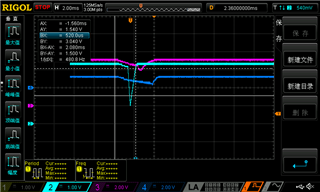
This is the waveform while resetting. Picture 1 is showed the whole, picture 2 is the zoom-in waveform. 1.2V drops a lot which may cause the reset.


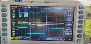
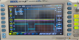
SYSCLK_ERR is the only fault they have found, some register cannot show the fault status due to the reset.

These are the questions:

1. Is there any risk about the SCH that will lead to the power increase while SPI working? This may lead to the PMIC overload and reset.

2. Is there any mechanism that if the SPI is too frequent to reset the PMIC?

3. Any possible reason and suggestions need to do for them?

Thank you so much.

Best regards,

Lanxi Li

  • Hi Li,

    Thank you for reaching out. I haven't been able to comprehend the problem. So I am trying to rephrase the problem for better understanding. 

    You are saying that customer has left NRES (7) pin open so that means PMIC is unable to get any reset from MCU, right. And another is that they are not using the interrupt pin (8) as well. Masked the SPI interface except chip select (NCS) and tried to run PMIC on default configuration. So, basically they tried to isolate the SPI communication and see if that is causing the problem right? This what I am understanding so please let me know if I am aligned with with problem statement or not. 

    In the Pic1, what is RESET waveform here, since you mentioned that pin is open.  

    Br,

    Ishtiaque 

  • 1、You are saying that customer has left NRES (7) pin open so that means PMIC is unable to get any reset from MCU, right. And another is that they are not using the interrupt pin (8) as well.

    Yes, We cut the connection to find the problem spot;

    2、Masked the SPI interface except chip select (NCS) and tried to run PMIC on default configuration. So, basically they tried to isolate the SPI communication and see if that is causing the problem right?

    Yes.

    3.In the Pic1, what is RESET waveform here, since you mentioned that pin is open.  

    It's DSP reset pin,it used to indicate the status of the DSP,trigger to obtain the PMIC power status when the DSP restarts.

  • Hi,

    Thank you for making it clear. In this case, SPI won't cause loading to PMIC. But looking at the schematics and plots nothing seems to be obvious but you also check whether overloading the Bucks or Boost is causing the problem. For that inductor current can be measurement to see if the PMIC is overloading. 

    Br,

    Ishtiaque  

  • But when we mask the NCS signal,the problem will not occur(PMIC power will not cut off)

    This problem doesn't happen all the time, it happens occasionally,sometimes it only happens hours apart

  • Hi, 

    So, you mean when the whole SPI communication is masked then problem does not occur. 

    But did you also happen to check overloading? does it cause any overloading issue when this problem occurs.

    Br,

    Ishtiaque 

  • 1、So, you mean when the whole SPI communication is masked then problem does not occur. 

    Yes.It only occurs when  the SPI  NCS signal is opend

    2、But did you also happen to check overloading? does it cause any overloading issue when this problem occurs.

    OK,we will to try it.

  • Hi,

    Yes please check if there is any overloading causing it and also PMIC won't reset because of SPI related errors, So, it could be from customer software as well. May be they can look at it from that perspective as well. 

    Br,

    Ishtiaque 

  • Hi,

    we had tested it today,the test records are as follows:

    1、Test whether the power supply is overloaded, Use an oscilloscope to test the current

    (1)PMIC 3.3V ouput,max current is 483mA

    (2)PMIC 1.2V ouput,max current is 600mA

    (3)PMIC 5V ouput,max current is 400mA

    We didn't find an overload problem

    2、We remove the DSP IC from the board,and use a signal generator simulates the SPI NCS signal to PMIC 

    after an hour,issue recurrence ,the PMIC power output  was off and reset.

    This rules out the software problem and overload problem 

  • Hi,

    Thank you for the measurements. 

    Can you please label the scope signals so that they can be distinguished and mention the time frame for reset signal and others as well.  Also can you confirm that VIO is 3.3V?

    In the last scope measurement, is the device loaded or not? And, if you could also check by apply cold spray to the device when running and see if it is caused by any thermal rise issue. 

    And in the last you can change the unit with new device on the same board and see if the problem occurs again and what is the behavior.  Let me know this by tomorrow if possible. 

    Br,

    Ishtiaque 

  • Hi,

    Just to add more here is that if you could share full schematic that be also helpful. Is there any pull ups on VIO pin and if yes what kind of pull ups they have it. 

    Br,

    Ishtiaque

  • Hi,

    Thank you for your help.

    We had tested three boards, and they all showed the same phenomenon.

    Could you please provide your email address? I will  send the full schematic to you.

  • Hi,

    Thank you for your reply. See my email below. 

    So how many devices have been tested? which exhibits same behavior. Have you tried to swap the device on the same board which shows this reset behavior not different board ? and if you could please label the last signal scope shot that would be helpful. 

    And also try to apply cold spray on device after half an hour interval and notice the behavior. This needs to be checked from thermal point of view as well?

    Also please confirm what were the loading conditions of your last measurements. 

    Br,

    Ishtiaque Panhwar

    i-panhwar@ti.com 

  • Hi Ya,

    After thoroughly analyzing the problem following questions and comments are provided to fully understand the nature of problem. 

    Suggestion: please re-run the test with modified setup

      • Disconnect BUCK1 as VIO supply
      • Use external 3.3V supply as VIO
      • Re-run the test in which DSP is disconnected from PMIC rails, and using signal generator as SPI NCS source

    Questions and comments based on already provided data:

    • SYSCLK_ERR: is customer reading the SYSCLK_ERR after recovery from NRES and power-down event by access to OFF_STATE_L register
      • Note: Detected clock error will cause device to shutdown and transition to OFF state, and we observe the rails are being disabled
    • What is the timescale for shown scope plots?
    • The 2nd scope plot is zoomed-in view of the NRES short pulse. Correct?
      • It appears that 1st NRES pulse is quite short. What is the scope timescale?
    • It was mentioned that SPI cycle is 7us? Does it mean that SPI NCS toggles every 7us or …?
      • Every toggle of SPI NCS will cause detected invalid SPI frame (short SPI frame is detected each time)
    • Is WD function enabled or disabled during this test?
    • Answer to Q1: potential risk is VIO supply load, which is BUCK1 3.3V rail
    • Answer to Q2: is WD function enabled or disabled? If enabled , WD cannot be serviced and WD accumulated errors would lead to reset
    • Answer to Q3: what is the purpose of this test with frequent and short SPI NCS pulses?
    • In captured scope plots, is signal with RESET label NRES output from PMIC?
      • If not, can you capture NRES output from PMIC together with power rail waveforms?
    • Please label waveforms in the latest scope plot.

    Br,

    Ishtiaque