This thread has been locked.

If you have a related question, please click the "Ask a related question" button in the top right corner. The newly created question will be automatically linked to this question.

BQ27Z561: Battery training procedure using BQ27Z561 fuel gauge IC and BQ Studio

Part Number: BQ27Z561
Other Parts Discussed in Thread: GPCCHEM, BQSTUDIO, , BQ78Z100, BQ28Z610,

Hi,

I have 2 Questions regarding battery training process, need expert's feedback for same.

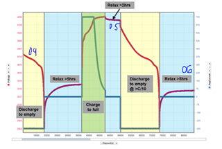
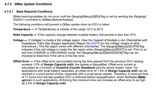
1) I found SLUA903 document to achieve successful learning cycle. The whole procedure is given in this document but i just want to know that do we have to follow all these steps simultaneously because whole procedure takes about 26-30 hours for full accuracy. I think it is impossible to sit these much hours continuously to complete the process.

2) I found chem ID using GPCCHEM tool but it is showing Best chemical ID max. deviation, % : 11.41, so can i work with 11.41% deviation or not?

And also recommended best chem ID is matches to NiMH chemical but i am using LiFePO4 battery, so in this case can i use this chem ID or not?

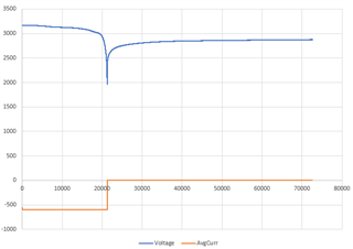
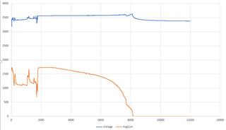
I am attaching this report, please go through it.

Chemistry ID selection tool, rev=2.53		
		
Configuration used in present fit:		
ProcessingType=2		
NumCellSeries=1		
ElapsedTimeColumn=0		
VoltageColumn=1		
TemperatureColumn=2		
CurrentColumn=3		
		
Best chemical ID : 6106	Best chemical ID max. deviation, % : 11.41	


Summary of all IDs with max. DOD deviation below 15%		
		
Chem ID	max DOD error, %	Max R deviation, ratio
6106	11.41	0.47
400	11.62	4.99
457	12.02	1.99
482	12.25	2.1
414	12.38	0.54
481	13.93	0.7
439	14.46	1.68
485	14.94	0.87
487	14.94	0.87
		
Max. deviations for best ID is within recommended range. Chosen best chemical ID is suitable for programming the gauge.		
		
		
Selection of best generic ID for ROM based devices like bq274xx		
		
		
Device / Family #1		
Generic Chem ID	Device/ Voltage/ Chemistry	max DOD error, %
354	bq27411-G1C: 4.35V LiCoO2	32.72
3142	bq27421-G1D: 4.4V LiCoO2	38.08
128	bq27421-G1A: 4.2V LiCoO2	43.12
312	bq27421-G1B: 4.3V LiCoO2	97.48
Best generic ID 354		
Warning: Generic ID Deviation is so high that it is most likely due to anomaly in the data. Please check that data files have recomended format, units and test schedule		
		
		
Device / Family #2		
Generic Chem ID	Device/ Voltage/ Chemistry	max DOD error, %
354	bq27621:  (ALT_CHEM2) 4.35V LiCoO2	32.72
1202	bq27621: (default) 4.2V LiCoO2	32.98
1210	bq27621:  (ALT_CHEM1) 4.3V LiCoO2	36.35
Best generic ID 354		
Warning: Generic ID Deviation is so high that it is most likely due to anomaly in the data. Please check that data files have recomended format, units and test schedule		
		
		
Device / Family #3		
Generic Chem ID	Device/ Voltage/ Chemistry	max DOD error, %
3230	bq27426: (default) 4.35V LiCoO2	30.5
1202	bq27426: (ALT_CHEM1) 4.2V LiCoO2	32.98
3142	bq27426: (ALT-CHEM2) 4.4V LiCoO2	38.08
Best generic ID 3230		
Warning: Generic ID Deviation is so high that it is most likely due to anomaly in the data. Please check that data files have recomended format, units and test schedule		


Thanks,

Parth

  • Hello Parth,

    1. The learning cycle process takes a long time but one does not have to be present all the time. There are specific steps with rest in between. The rest periods can be longer than specified, so you can come back and proceed the next day.

    2. Make sure to remove any protectors. Logs from bare cells must be used for GPCCHEM matching.

  • Hi,

    There was no protectors at all and also i had followed whole procedure properly to get chem ID.

    Now i am just concerned whether i can use this chem ID or not which is showing me 11.41% deviation and best chem ID recommended is matching to NiMH chemical but i am using LiFePO4 battery.

    Thanks,

    Parth

  • Hello Parth,

    Can you send the manufacturer/model of the battery and the datasheet? Is it listed in bqStudio? Latest chemistry update for bqStudio  www.ti.com/.../GASGAUGECHEM-SW

  • Yes, all recommended IDs are available in bqstudio.

    I am just confused whether i can use this chem ID or not, because it has MiNH chemical and 11.41% deviation.

    Battery Model : 18650/3.2V/1500 mAH, LiFePO4

    Here, i am sending you datasheet of the battery, please go through it.

    .1500 mAH Battery.pdf

  • Hello Parth,

    You cannot use that ChemID. It is too different. I will check with the team on the specific model

  • Since LFP has much higher voltage compared to NiMH, detecting NiMH chemistry indicates that something was dragging the voltage down. One possibility is very high contact resistance, which would add a lot of IR drop. Too high discharge rate could also contribute.
    I would try to run this test with C/10 discharge rate, and trying to eliminate any additional resistance. The tool does compensate for IR drop, but it only works if it is just the drop from the battery itself (so it has certain shape of R vs SOC curve, same as in  chemID it is matching), other added resistances will distort the correction.

  • Can i use 400 ID or any other ID from this same report which is for LiFePO4 chemical.

    Chemistry ID selection tool, rev=2.53		
    		
    Configuration used in present fit:		
    ProcessingType=2		
    NumCellSeries=1		
    ElapsedTimeColumn=0		
    VoltageColumn=1		
    TemperatureColumn=2		
    CurrentColumn=3		
    		
    Best chemical ID : 6106	Best chemical ID max. deviation, % : 11.41	


    Summary of all IDs with max. DOD deviation below 15%		
    		
    Chem ID	max DOD error, %	Max R deviation, ratio
    6106	11.41	0.47
    400	11.62	4.99
    457	12.02	1.99
    482	12.25	2.1
    414	12.38	0.54
    481	13.93	0.7
    439	14.46	1.68
    485	14.94	0.87
    487	14.94	0.87
    		
    Max. deviations for best ID is within recommended range. Chosen best chemical ID is suitable for programming the gauge.		
    		
    		
    Selection of best generic ID for ROM based devices like bq274xx		
    		
    		
    Device / Family #1		
    Generic Chem ID	Device/ Voltage/ Chemistry	max DOD error, %
    354	bq27411-G1C: 4.35V LiCoO2	32.72
    3142	bq27421-G1D: 4.4V LiCoO2	38.08
    128	bq27421-G1A: 4.2V LiCoO2	43.12
    312	bq27421-G1B: 4.3V LiCoO2	97.48
    Best generic ID 354		
    Warning: Generic ID Deviation is so high that it is most likely due to anomaly in the data. Please check that data files have recomended format, units and test schedule		
    		
    		
    Device / Family #2		
    Generic Chem ID	Device/ Voltage/ Chemistry	max DOD error, %
    354	bq27621:  (ALT_CHEM2) 4.35V LiCoO2	32.72
    1202	bq27621: (default) 4.2V LiCoO2	32.98
    1210	bq27621:  (ALT_CHEM1) 4.3V LiCoO2	36.35
    Best generic ID 354		
    Warning: Generic ID Deviation is so high that it is most likely due to anomaly in the data. Please check that data files have recomended format, units and test schedule		
    		
    		
    Device / Family #3		
    Generic Chem ID	Device/ Voltage/ Chemistry	max DOD error, %
    3230	bq27426: (default) 4.35V LiCoO2	30.5
    1202	bq27426: (ALT_CHEM1) 4.2V LiCoO2	32.98
    3142	bq27426: (ALT-CHEM2) 4.4V LiCoO2	38.08
    Best generic ID 3230		
    Warning: Generic ID Deviation is so high that it is most likely due to anomaly in the data. Please check that data files have recomended format, units and test schedule		


    Thanks,

    Parth

  • Yes, in absence of another test data, 400 is the best ID from the report, and it is LFP so it makes more sense to use it. Max error level is typical for LFP because it has very flat voltage profile. 

  • But it has DoD Deviation of 11.62% and R deviation is 4.99 as shown in report, so can i go ahead with learning cycle procedure with this much deviations. Because i have studied that in order to accurately perform successful learning cycle first we need to program perfect matching chem ID into gauge IC.

    Thanks,

    Parth 

  • Because of extreme flatness of LFP, even specially released chem IDs have from 10 to 18% Max. deviation for 1mV measurement error. So 11% is quite normal for LFP. Note that this is just "max" deviation (there are areas with much lower value) and our gauges uses special algorithm which will give low weight to reading at "worst" OCV regions, so they will not dominate overall accuracy.

  • Thank you so much for your quick replies.

    Next question comes for learning cycle process.

    Can you tell me what parameters should i have to set into gauge data memory before starting this process.

    Thanks,

    Parth

  • Hello Parth,

    Please follow this app note which describes how to complete a full learning cycle.

    https://www.ti.com/lit/an/slua777/slua777.pdf

    Regards,
    Jose

  • This app note shows the procedure for bq28z610/bq78z100 but i am using bq27z561, so can i use this app note or not.

    Thanks,

    Parth

  • Hello Parth,

    It is the same principle. Typically, for a learning cycle you'd want to configure the following parameters:

    - design capacity, charge termination taper current, discharge current threshold, charge current threshold, quit current and term voltage.

    Should you have any questions in the process, please feel free to reach out.

    Regards,
    Jose

  • Hii,

    Can you please verify our design parameters which we have selected as per calculations and our requirements.

    Charge termination tapper current = 30mA

    Discharge current threshold = 5mA

    Charge current threshold = 250mA

    Quit current = 150mA

    Here i am attaching datasheet of the battery which you can refer to verify these parameters.

    6835.1500 mAH Battery.pdf

    Thanks,

    Parth

  • Hello Parth,

    Please ensure the following occurs:

    1- Taper Current > Chg Current Threshold > abs(Quit Current)
    2- DSG Current Threshold > abs(Quit Current )

    where abs is absolute value

    Also, it is recommended to do a quit current of C/20. In your case -> 1500/20 = 75 mA

    Regards,
    Jose 

  • Hii,

    I found one of the document for learning cycle provided by ti where all these parameters are explained by taking example values.

    In our case we are using two 1500 mah batteries connected in parallel so total battery capacity is 3000 mAH.

    By using this capacity we have calculated charge termination tapper current = 3000/20 = 60 mA, so we are taking it 70 mA as suggested in this document to keep this value slightly higher than C/20.

    That's why we are thinking to use these same values given in this document as below :-

    Charge termination tapper current = 70 mA

    Discharge current threshold = 45 mA

    Charge current threshold = 40 mA

    Quit current threshold = 10 mA

    Can we use these values?

    Here i am attaching the link of this document for your reference where all these parameters are explained from section 3.2 onwards.

    https://www.ti.com/lit/an/slua777/slua777.pdf?ts=1667208114046&ref_url=https%253A%252F%252Fwww.google.co.in%252F

    Please verify these parameters and let me know whether we can use these same values or not!

    If no, then please guide me to calculate proper values by giving me some equations/ examples/ reference links/ documents.

    Thanks,

    Parth

  • Hello Parth,

    Yes, those values should work. You can use them.

    Regards,
    Jose

  • Thank you!

    I will try it and will update the status.

  • Sounds good.

    Regards,
    Jose

  • Hii,

    I tried to perform learning cycle but every time i stuck at the 4th cycle of relaxing battery where battery update status should change to 05 from 04. I am unable to do further procedure from here because update status is not changing to 05 from 04, i tried everything but didn't worked. Need your help to do so.

    I also waited for more then 48 hours to update the status from 04 to 05 as it was suggested in one of the thread by ti expert to wait for 48 hours for LFP battery but it did not worked.

    Till here, all steps worked. All the bits were changed as per suggested in reference manual. I am using this reference manual to implement learning cycle.

    https://www.ti.com/lit/an/slua777/slua777.pdf

    I am using two LFP batteries (1500 x 2 = 3000mAH) Connected in parallel having 3.65V.

    I obtained Chem ID successfully using GPCCHEM and also programmed it into fuel gauge IC.

    Below are all parameters which i updated into data memory of fuel gauge IC before starting learning cycle :

    Sr. No. Parameters Value Description
    1 Design Capacity mAH 3000  
    2 Design Capacity cWH 1095 3 * 3.65 * 100  (3000mAH * 3.65V * 100 ) -> Centiwatt hours
    3 Charge term taper current 250 mA
    4 Discharge current threshold 200 mA System required minimum current
    5 Charge current threshold 180 mA  
    6 Quit current 150 mA  
    7 Term Voltage - IT Config 3000 mV Termination voltage
    8 Charge Term Voltage/Taper Voltage 2900 mV Charging Termination voltage - 100mV less then total battery capacity
    9 FC Set Voltage threshold 3620 mV  
    10 FC Clear Voltage threshold 3000 mV  
    11 FD Set Voltage threshold 3000 mV  
    12 FD Clear Voltage threshold 3100 mV  
    13 Cell1 Chg Voltage at EoC - IT Config 2990 mV

    10mV less then total battery capacity

    I had also tried it with other values but it was failed before this cycle which is as below:

    Charge term taper current = 70 mA

    Discharge current threshold = 45 mA

    charge current threshold = 40 mA
    Quit Current = 10 mA

    We had reviewed these values above, but it did not worked.

    Using these values, FC bit did not set at after charging the battery to full so i changed these values.

    Here i am attaching datasheet of the battery and all the logs which i have collected during learning cycle for your reference.

    Please go through it and give me some solution as soon as possible as i need to complete it in short time.

    7776.1500 mAH Battery.pdf1423.DataMemory.zipBatteryLearningFianlDATA.xlsxBatteryLearningFinalData.txt

    Thanks in advance,

    Parth

  • Hello Parth,

    I tried to perform learning cycle but every time i stuck at the 4th cycle of relaxing battery

    What do you mean by 4th cycle of relaxing battery? There are only three relaxes required for learning cycles. The learning cycle procedure should look like the one below


    Assuming you are talking about after doing the first discharge, and relaxing. The reason why you are not seeing update status to go from 04 to 05 is because Qmax was never updated. Please monitor VOK and RDIS bits while in relax after the first discharge.

    What prevents Qmax from updating?


    Recommendations:

    1- Why is Cell1 Chg Voltage at EoC so low? EoC stands for End of Charge. This voltage must be close to the voltage when VCT occurs or FC. Depending on configuration.

    2- Please set LFP_RELAX bit in IT Gauging Configuration register.

    3- Charge term voltage is too high. VCT- Valid Charge termination is set when Voltage + Charge Term Volatge >= charging voltage along with a taper current condition. In the current settings, the voltage condition in the VCT will always be true. A typical charge term voltage is 100 mV and lower than 100 mV. Please refer to 9.8 Valid Charge Termination in the TRM for proper VCT.

    Regards,
    Jose

  • Hello,

    In both relax cycles (Relaxing after first discharge as well as then Relaxing after charging the battery to full capacity) VOK and RDIS bits were cleared at the end of relax cycles and also i relaxed the battery till REST bit got set as suggested in reference manual although update status did not changed to 05 from 04.

    I am talking about second relax cycle after charging the battery to full capacity where update status should change to 05 from 04, but it did not.

    Other questions :

    1 - Do i need to wait for 48 hours for Qmax update for LFP Battery?

    2 - In which cycle i have to set LFP_RELAX bit?

    Thanks,
    Parth

  • Hello Parth,

    1- You do not need to wait 48 hours for Qmax update. You need to wait at least 5 hours in all relax periods.

    2- LFP_RELAX bit should be set and configured in all cycles. The impedance track based gauges have a harder time taking OCV measurements with LFP batteries due to its nature flat OCV curve. This bit lets the gauge know that "we are dealing with LFPs"

    Please try the recommendations and see if anything changes. You only need to (discharge -> relax -> charge -> relax -> discharge -> relax) for a learning cycle.

    Please ensure VCT is properly configured.

    Regards,
    Jose  

  • Just a minor edit on my reply. Please ensure to rest 24 hours after charge.

    Regards,
    Jose

  • Hello,

    I have some queries.

    1) Do i need to wait for 24 hours even though my battery get relaxed before 24 hours where VOK & RDIS bits gets cleared, REST bit is set and also update status changes to 05 from 04?

    2) As you suggested to set LFP_RELAX bit in all cycles but In my case there is no LFP_RELAX bit, i am using BQ27Z561-R2 fuel gauge then what should i do? i am attaching image where you will see that there is RSVD(Reserved) bit instead of LFP_RELAX bit in IT gauging configuration.

    Thanks,

    Parth

  • Hello Parth,

    1- Because of the flat nature curve of LFPs, it is recommended to wait 24 hours after charge, otherwise the gauge might not realize the full capacity at discharge.

    2- 

    I will send you the bqz file version I have via internal message.

    Regards,
    Jose

  • Sure, Please send me that file via internal message.

    Thanks,

    Parth

  • Parth,

    I just sent it with instructions.

    Regards,
    Jose

  • Received it. 

    Thanks for the support. 

    I will try next iteration with this file and all recommendations you gave above. Hoping to get successful learning cycle this time. 

    Thanks,

    Parth

  • Please reach out should you have any questions.

    Regards,
    Jose

  • Sure, i will try again and will update the status. 

    Thanks, 

    Parth

  • Hello,

    I tried to implement learning cycle today but i failed again so i need to ask some queries to you.

    1) I failed at the 3rd step of charging, where charging termination did not occurred. VCT, MCHG and FC bits did not set at the end of charging the battery, so what could be the reason behind that. I changed Charge term voltage offset = 100mV as you suggested above and i also set LFP_RELAX bit this time in all cycles as we discussed although it failed.

    2) I have set charge term charging voltage = 3630mV so is it correct or not? I am using 2 x 1500 = 3000mAH LFP batteries connected in parallel having 3.65V.

    3) I am unable to do current/voltage calibration. Here i am getting error that calibration - A read of data written failed comparison, so what could be the reason behind this?

    4) If i fail at any step of battery leaning then do i need to start over from the first step again? As i have failed at the 3rd step of charging this time then do i have to perform all steps from the starting again?

    5) If i successfully complete the learning cycle then full charge capacity (3000mAH) will be updated as per my battery capacity, Right? so that i can get correct battery percentage.

    6) The value of cycle count increment after every cycle of learning? what if it does not increments at some cycle?

    7) I am discharging the battery by C/2 rate at the first step of discharging the battery, is there any problem with that?

    8) What is the recommended charging and discharging rate for last cycles of charge-relax-discharge to get update status = 0E from 06 and how much time i have to relax the battery at this step? 2 hours of relax time is fine or not?

    9) I need bqz file for LFP_RELAX setting for bq27z561 instead of bq27z561-R2, can you send me that?

    Thanks,

    Parth

  • Hello Parth,

    1- Please send your configuration gg file to further look (please send the configuration file used that describes your scenario). 

    2- Charge Term Charging Voltage is used if Taper_VOLT is set, otherwise charging voltage is used. 

    I am using 2 x 1500 = 3000mAH LFP batteries connected in parallel having 3.65V.

    Design capacity should be doubled. 

    3- A quick workaround would be to set Valid Update Voltage to 0mV


    4- Because the gauge does not learn Qmax until it finishes step 3, I recommend you start again. 

    If Learning cycle would have failed at step 5, then you could have started at step three because the gauge already knows Qmax.

     5- FCC will always be a little less than Qmax. After you successfully complete the learning cycle, Qmax will be updated and resistance table will be updated. With this information, the gauge will be able to report the correct FCC, RM, and SOC.

    6- Cycle Count is used to update the degradation of the battery. This parameter is used for future Qmax updates, the gauge does Qmax updates in the field after the test phase. I do not anticipate this parameter to stop incrementing.

    7/8 -  C/10 minimum, usually C/5 to C/7 is best for discharging.

    C/2 for charging. 

    There's no need to keep changing the rates at each step. I would say, choose from C/5 to C/7 for discharging, and C/2 for charging.

    9- Can you clarify why you would need to downgrade on versions?

    Please see this below. After charge, please relax 24 hours. Other relaxes can be 5 hours.


    Regards,
    Jose Couso

  • Hello,

    1) Sure

    BatteryLearning.logBatteryLearning.zip

    9) Because i have BQ27Z561 Hardware IC, i had mistakenly asked for the BQ27Z561-R2 file. Also in that version i had successfully completed upto 3rd step but using this file i failed at the 3rd step only.

    I have another queries..

    i) Can i load BQ27Z561R2 file into BQ27Z561 IC? Will it work or not?

    ii) Because i have only BQ27Z561 IC only for now and there is not LFP_RELAX bit in BQ27Z561 BQZ file which i have. So what should i do now? If you can share BQZ file having LFP_RELAX bit configuration for BQ27Z561 then it would be great.

    Thanks,

    Parth

  • Hello Parth,

    1) I will check on the provided files and get back to you.

    9) I will send you a private message regarding on this.

    Regards,
    Jose Couso

  • Hello,

    Today also i failed at the same 3rd step of battery charging where VCT and FC bit did not set.

    I don't understand why i am failing. I have set values of all required parameters into data memory as we discussed above.

    Please tell me if i need to change any value before starting learning cycle.

    Sr. No. Parameters Value Description
    1 Design Capacity mAH 3000  
    2 Design Capacity cWH 1095 3 * 3.65 * 100  (3000mAH * 3.65V * 100 ) -> Centiwatt hours
    3 Charge term taper current 250 mA
    4 Discharge current threshold 200 mA System required minimum current
    5 Charge current threshold 180 mA  
    6 Quit current 150 mA  
    7 Term Voltage - IT Config 3000 mV Termination voltage
    8 charge term voltage offset 100 mV
    9 FC Set Voltage threshold 3620 mV  
    10 FC Clear Voltage threshold 3000 mV  
    11 FD Set Voltage threshold 3000 mV  
    12 FD Clear Voltage threshold 3100 mV  
    13 Cell1 Chg Voltage at EoC - IT Config 3630 mV

    10mV less then total battery capacity

    Also i am setting LFP_RELAX bit now and voltage charge term tapper voltage set to 100 mV as you suggested and charge term charge voltage = 4400mV.

    Do i need to set some other parameters for same?

    Thanks,

    Parth

  • Hello Parth,

    I double checked your configuration file, please see below what I found.

    1- Mfg Status init is set to 8, by default this is 0. The eighth bit is a reserved bit. Hence it shouldn't be touched.

    2- For VCT the gauge checks: 

    AverageCurrent() < Charge Term Taper Current             AND           Voltage() + Charge Term Voltage ≥ ChargingVoltage() AND [TAPER_VOLT] = 0

    Note: if TAPER_VOLT is 1, then the gauge uses Charge Term Charging Voltage, otherwise chargingVoltage() is used. Your current settings state that TAPER_VOLT = 0

    3- Clear voltage threshold in FC is set to 3000 mV, this is wrong, as FC will only clear when gauge is at the terminate voltage level. This should be set to 3520 mV, please see below.


    4- TC configuration is not correct. Right now the Terminate charge alert is set for when the gauge reaches 4400 mV, which never happens since your max voltage you want to charge up to is 3620 mV. I would set this to 3620 mV and clear threshold to 3520 mV. Please see below


    5- Currently, design voltage is set to 3850 mV, I would set this value to the max voltage you want the cell to be charged up to.

    6- Even though you don't know the Qmax of the cell yet as your are doing the learning cycle for this same purpose, I would still change Qmax to a reasonable value which will be close to design capacity. This parameter is "Qmax Cell 1"

    7- Please change load mode to 0 if you are using constant current.

    Regards,
    Jose Couso

  • Hello,

    I am not setting Mfg Status init, it is getting set automatically as soon as i start learning cycle and set GAUGE_EN bit in the 1st step.

    Thanks,

    Parth

  • Hello Parth,

    Please disregard Mfg Status init if it is setting automatically.

    Regards,
    Jose Couso

  • Hello,

    I have completed learning cycle upto 4 steps thanks to you but now i have questions from 5th step onwards to ask you.

    1 - Does update status changes to 06 from 05 at the end of battery discharging (after 5th step) or it gets updated after relaxing the battery for 5 hours (after 6th step)?

    2 - What should i do if it doesn't change to 06? Should i have to do charge-relax-discharge-relax only or do i have to start over from the 1st step again?

    3 - How can i come to know that Ra table updated at this step is correct/proper as it should be as per battery? Because Qmax update is visible in bqstudio so we can verify that but for Ra table verification what should i do?

    4 - How to verify that remaining capacity is correct which is updated after successfully implementation of learning cycle? 

    5 - After completion of learning cycle 3 files gets generated in golden image, which is gm.fs, df.fs and bq.fs so in this which file should i have to use to program it into fuel gauge over I2C in order to fetch proper remaining capacity from fuel gauge?

    Thanks,

    Parth

  • Hello Parth,

    I am glad you could make it up to update status: 05. This means the gauge already learned Qmax. Now, the gauge needs to learn the resistance table to update. For resistance update, make sure RDIS bit is not set. 

    1- It should be updated at the end of discharge once it changes operation state to RELAX. For this, RDIS must not be set and make sure discharge is not interrupted. 

    2- No need to start from beginning, all you need to do is ensure the cell is fully charged and relax for 24 hours due to LFP chemistry and then discharge to learn cell resistance.

    NOTE: A typical C/5 rate is recommend, but the rate can be as low as C/10. If using a C/10 load, make sure the gauge sees that the current is at least C/10, if the current is any lower, resistance updates does not occur

    3- You can verify Ra table by exporting configuration gg file before and after update status is 06. 

    4- After the successful learning cycle, you can test RM by charging and discharging the cell (in this case there's no need to wait 24 and 5 hours as gauge is not learning, two hours wait is enough). You can monitor RSOC, RM, FCC during test stage.

    5- The bq27z561 is a flash based gauge. For flash gauges, you can export .bq.fs, .bq.fs, or even the srec file. 

    - Configuration files for flash gauges: *.df.fs

    - Firmware and configuration files for flash gauges: *.bq.fs

    - srec files also contain firmware and configurations. 

    For more information on this, please follow this app note.

    https://www.ti.com/lit/an/slua801/slua801.pdf?ts=1668527977464&ref_url=https%253A%252F%252Fwww.ti.com%252Fproduct%252FBQ27426

    Regards,
    Jose Couso

  • Hello,

    1 - So it means i have to wait for 5 hours after battery discharging till REST bit gets set, Right?

    Because discharging is completed but still update status was not changed to 06 from 05.

    Also i had noticed that RDIS bit was set automatically during discharging (5th step), i had not set it manually, so what could be the reason behind that? 

    2 - What parameters should i have to reconsider if i fail at this step?

    5 - So in my case i have to use df.fs file, Right? 

    Because bq.fs is having large size so it would be difficult to program this file over I2C using any microcontroller.

    Thanks,

    Parth 

  • Hello Parth,

    1- Resistance updates will occur during charge, there's no need to wait 5 hours.

    RDIS should get cleared in RELAX mode, make sure you wait 24 hours after charging and monitor RDIS.

    2- Make sure IT-impedance track is enabled and RDIS is clear

    5- You can use any of the above file streams, the difference is if firmware is required to upload along with configurations at mass production.

    Regards,
    Jose Couso

  • Hello,

    1- I am confused whether resistance update occur during charge (3rd step) or charge or discharge (After 5th step).

    RDIS bit was cleared in relax mode but it got set automatically during discharge, i don't understand why it happened.

    What are the possible reason of RDIS bit getting set automatically and how to prevent that?

    2 - I don't understand why RDIS bit got set during discharging, what could be the reason behind that?

    3 - Unfortunately i could not complete 5th/6th step where update status should have been changed to 06, please help me to find the solution for same.

    For now i am trying with charge-relax for 24 hours - discharge by C/5 rate again meanwhile please provide me some solution to get update status = 06.

    Here i am sharing all logs from discharging (5th step) having relax mode logs also to find some solution.

    BatLearningTake3.logBatteryLearningData from discharging step.zip

    4 - Something strange happened during learning cycle. After i failed at the 6th step (Relax after discharge) where update status was not updated to 06 so i started again from step-3 of battery charging but here after completing full charging update status changed to 06 so can you tell me what is happening exactly? Am i going into right way or what? Because update status changed to 06 here instead it should have changed at the 5th/6th step, so do i have to consider that if update status status is changed to 06 then Qmax and Ra table has been updated correctly or do i need to do something else?

    5 - Also Qmax was updated to 2982 mAH after 3rd step of battery charging previously but it has changed to 2805 mAH now after i started again when i failed at the 6th step (where update status should have changed to 06 but instead it got changed to 06 after i charged the battery again), so can you tell me why it got reduced? My battery original capacity is 3000 mAH so what should i do now?

    6 - I can see here that some of the value in Ra_table got changed when i charged the battery again, what is the reason behind that?

    Here i am sharing latest logs for your batter understanding after i charged the battery again and relaxed the battery for some time.

    BatLearningAgain.logBatteryLearningData after battery charging.zip

    7 - Considering everything is going correctly after running extra charge cycle then in relax mode do i have to wait for 24 hours or 5 hours are enough to change update status from 06 to 0E for cell balancing before releasing golden image for mass production?

    I am unable to understand what is happening and do i need to change anything or whatever i have done till now is correct as it should be? that's why i have to ask lot of questions, pardon me for that!

    I am just confused/concerned about update status value, it did not changed to 06 after 5th & 6th step (After battery discharging and relaxing) but it got changed to 06 when i charged the battery again.

    Thanks,

    Parth

  • Hello Parth,

    Resistance table should only update during discharge. 

    Starting from the first files you uploaded "BatLearningTake3.logBatteryLearningData from discharging step.zip", let me explain what I see.

    Looking at the log file, this is what it shows.


    In the above picture, it can be seen a discharge-relax. I went ahead and looked at the configurations files to see if any updates had occur in the resistance table. Please see below.


    As seen above, a resistance table update occurred during the discharge cycle.

    Now let's look at files: "BatLearningAgain.logBatteryLearningData after battery charging.zip"

    This sis what the log shows:


    As it can be seen above, the charging current was not constant current and very unstable compared to the discharge cycle. When the gauge is in learning stage, a constant current must be provided. 

    Looking at the configuration files to see if resistance table updated during charge (which should not occur), This is what I see.


    Please notice above how the auto calibration feature trigger since current was unstable. Unstable current causes gauging problems and the gauge responds accordingly, this is why the gauge  reduced Qmax Cell 1 value. 

    It seems like the gauge is learning Qmax and Ra table at the proper state of operation. The difference is that the Update Status is not synchronized with the steps you are performing, but I wouldn't be worried about sync. I would worry about charging and discharging with constant current.

    Note: Qmax and Ra values are constantly updated in the field, so if after successful learning cycle you notice changes, this is normal. In fact, this is the key of Impedance Track algorithm. This algorithm learns Qmax and updates Resistance Table periodically, this way the gauge will know how degraded the battery is, and is able to report accurate RSOC, FCC, RM, etc.

    7- You can try waiting 5 hours in each RELAX since the gauge already learned Qmax and Ra.

    Regards,
    Jose Couso

  • Hello,

    1 - Discharge current was constant then why update status did not changed to 06 in discharge stage only?

    2 - What should i do now to update proper Qmax value as is has been reduced due to inconstant charging current as you said?

    Do i need to run some another cycles to get proper battery capacity/Qmax?

    3 - In order to update update status to 0E from 06, which extra cycle i need to perform more? Charge-relax has been already performed after 6th step (Relax after battery discharging)?

    7 - But Qmax has been reduced, so what should i do about that?

    Updating status to 0E is required for mass production use, Right? and i need to set proper Qmax value as per battery capacity, Right?

    Please give me some suggestions for same.

    Thanks,

    Parth

  • Hello Parth,

    1- It is hard to explain why update status did not change to 06 with only one discharge cycle. I do not have the history when Qmax updated or when you started the whole learning cycle process. I know the Update Status not being synced with updates might be confusing, but I wouldn't worried much about this as we already know the gauging is learning resistance table and Qmax periodically. 

    2- The gauge already updated a proper Qmax value "3088 mAh". You can use this value as a starting point for when testing the gauge accuracy before mass production. No need to run more learning cycles.

    Note: When I say testing the gauge, I mean to run the scenarios the gauge will be exposed to in your application. The learning cycle is just for the gauge to learn Qmax and Ra table and with these parameters, the gauge learns the cell capacity and its resistance for best gauging prediction.

    3- To get update status to 0E, please charge the cell to full, RELAX for 5 hours, discharge the cell to empty (at this point Update Status should be 0E), RELAX for 5 hours. Ensure IT is enabled.

    Updating status to 0E is required for mass production use, Right? and i need to set proper Qmax value as per battery capacity, Right?

    Are you using 2 S configuration? 0E means cell balancing has been enabled.

    Remember to run some tests on the gauge before mass production. At the test stage, some parameter might be tuned for your application. When I say test, I say putting the gauge under the required application temperature and doing charge-relax-discharge cycles and monitoring RSOC and checking that there are no drops or jumps. 

    Regards,
    Jose Couso