This thread has been locked.

If you have a related question, please click the "Ask a related question" button in the top right corner. The newly created question will be automatically linked to this question.

DCP020505: test setup for the galvanic isolation test of the DCP020505U

Part Number: DCP020505

Number: CS1340664
Contact: Achim Stösser
First name: Achim
Last name: Stösser
Short description: test of the galvanic isloation, reopen case number CS0723404 see attachment
Email: stoesser.achim@addi-data.com
Company: ADDI-DATA GmbH
Company phone:
Language: English
State: Open
Provide case details or comments:
Dear technicans
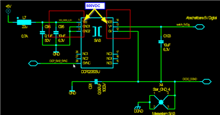
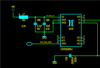
in the CS0723404 we discusse the test setup for the galvanic isolaiton test of the DCP020505U


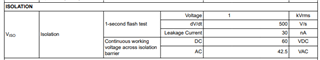
What we want to test is that the complete circuit  with DCP0505U and other digital isolators  withstand 500VDC for 1 sec.
You suggested us to reduce the complete test duration to max 1s.
How is this possible to realize? If max dV/dt is 500V/s we can't reach 500V with a rise time < 1s.
To test this we use a special High Voltage Test device. we can define the rise time ( min 1s) , the hold time(min1s)  and the falling time ( min 1s). We can define the max allowable current to 0.1mA
If the High voltage tester shows a current 0,11mA  or more but 500VDC is ok what does it mean for the component?
Thanks a lot
 Achim Stösser

  • Hello Achim,

    I believe you are referring to this thread: (+) DCP020505: Test isolation voltage - Power management forum - Power management - TI E2E support forums

    For High-Voltage Isolation testing, section 7.3.1.5 of the datasheet specifies that repeated high-voltage testing should be limited. If this is absolutely required reduce the voltage by 20% from the specified test voltage with a duration limit of one second per test.

    Regards,

    Harrison Overturf 

  • Hello Harrison

    I understand that I have to reduce the Testvoltage by 20%. We only test with 500 V not 1KV, so we are 50% form the 1kV.

    Normaly if its ok we only test one time!

    To respect the dV/dt from the datasheet  we need min 1 s rise time to reach the test voltage of 500V that we then keep for 1s and we need 1s to power down to 0V. Normaly a slower rising should be better then 500V/s ?

    So  ìs it Ok to define 1s rise time ( 0--> 500V) , 1s hold/duration (500V) and 1s falling time ( 500V --> 0V)?

    In the datasheet the leakage current is specified with 30nA !

    I can set my test unit only min to 10µA  to break the test before reaching 500V. What does it mean if the test is valid ( the 500V is reached) and the leakage current measured is by about 50µA ?

    Thnask for you work

    Regards Achim Stösser

  • Hello Achim,

    The sequence you describe sound reasonable based on the specifications offered in the electrical characteristics table. 

    In terms of the leakage current, what is your test setup? 

    Regards,

    Harrison Overturf 

  • Hi Harrison

    we test the DCP020505U as single device with 500V DC wiht 0,04mA max. acceptable  leakage current. If test is Ok we solder it on the PCB

    and test the whole board (with additional  galvanic isolated datacouplers, valid isolation test with 500V was done before, without DCP020505U) again with 500V DC to guarantee the correct working of the galvanic isolation

    What is the maximum acceptable leakage current?

    thanks

    Achim

  • Hello Achim,

    Across which pins of the DCP020505U do you apply the 500VDC? Can you share a schematic of the test situation? 

    The datasheet lists the maximum leakage current as 30nA. 

    Regards,

    Harrison Overturf

  • Hi Harrison

    if soldered on the board we test between this pins (1,2,3, is one terminal - 12,13 is the other terminal) , Sync is not connected and therefore no  high Voltage is on this pin

    if only the part outside the board is tested (before the soldering on the board)  one terminal is Pin 12,13,14,15,16,17 and the other terminal is pin 1,2,3,26,27,28

    best Regards Achim

  • Hi Achim,

    Thanks for sharing, when you test the device outside the board you include the SYNC pin as well? 

    What is the measured leakage when this pin is excluded from testing?  

    Regards,

    Harrison Overturf 

  • Hi Harrison

    there is no difference with or without the sync pin,  test on one of the DCP020505,  I set the limit for the leakage current to 0,06mA / 60µA

    and the 500V is reached,

  • Hi Achim, 

    Understood, have you tried testing between pins 2, 3 and pin 12 only? Also do you notice a change in impedance between any pins after the high voltage test is performed?

    Regards,

    Harrison Overturf 

  • Hi Harrison

    sorry for the late reply ,I was some days off

    there is no difference between test  on Pin2,3  and 12 or with all pins connected or without sync pin.

    I tested about 10 parts more with following result

    3 of them succeed  with a limit of 0.1mA leakage current ( smallest adjustable current on our HV tester is 0,01mA)

    7  failed with up to ~5-9mA at 100V max isolation voltage (because there was a  break from the HV Tester when I tested with 500V, I searched for a lower voltage to see differences betwenn teh 7 components)

    The questions for us is now are this 3  parts OK  considering the isolation voltage? The voltage output ( DCP020505 = 5,6V with a load of some 10mA) is working correct.

    And what is the max. leackage current where we can say, that the isolation voltage from 500V ist OK?

    Thanks a lot

    Achim

  • Hi Achim, 

    I need to reach out to some members of the team internally to discuss this. Please expect a reply in 1-2 business days. 

    Regards,

    Harrison Overturf 

  • Hi Harrison

    I've ,made some further tests and thougt about a simulation with LTSpice

    I there a Spice model for the DCP020505U/ DCP020515DU ?

    If I take a simple reduced circuit with 1* DCP020505U and 2* DCP020515DU and 3 HV Ceramic capacitor with 47nF

    is it possible to simulate the current  during 1s rise ramp ( to 500V)  1s hold time (500V) and 1 s falling ramp(back to 0V)?

    Source is a DC  high generates this 500V Voltage

    Regards Achim

  • Hi Achim,

    Sorry that we do not yet have a spice model to share, and I don't think Spice simulation is a right tool to investigate the isolation issue.  

    May I bother you to share a photo picture of your setup, when you test the DCP020505 device standalone, or on your circuit board?  I would like to see how the Hotpot instrument is hooked up to the device in standalone or soldered on your circuit board. 

    By the way, the 500V/s slew rate is the maximum limit for the flash test and the actual setup should take a slower slew rate,  

    Thanks,

    Youhao

  • Hi Youhao

    this is our " adapter"  for the test of the component


    this is the board with 1* DCP020505U and 2 DCP020515DU, the red line shows the isolation barrier with > 3.2mm distance for 1000V, we only test with 500V DC

    Regards Achim

  • Hi Achim,

    Thank you for the info.  I can see that the 0.047uF capacitors across the isolation boundary are installed.  These capacitors will also draw current when you apply the HV voltage at a slew rate. 

    3x 0.047uF x 500 V/s = 71 uA

    Therefore, the 60uA limit setting on the tester is not enough.

    When you mentioned two days ago that you tested 10 parts with 7 failed and 3 passed, were these parts tested standalone or they were tested on your PCB?

    I am sending you a PMS invitation, hoping to contact you from there, such that we can move faster in the investigation.  

    Thanks,

    Youhao

  • Hi Yahou

    I 'm located in Europe/Germany.

    the 10 parts I have testet them stand alone.  

    in all 7 cases the high voltage brakes, respectivly the HV Tester stops immeditately.

    With the LTSPIce Simulation of just the capacitors I saw that there is a current of near 80µA .

    So I set the max current testing the parts to 0.5mA , same value for the test of  the boards .

    I use some addional parts from our stock, check them first to be under the 0.5mA limit . I tested two boards without the parts to be under the 0.5mA limit

    I saw no error on the boards without the part , max current is under 0.1mA .  I succed with one of the two succesfully  tested parts .

    conclusion of my isolation test: when I set the max current to 0.5mA and the test of the board with teh part is succesful the isolation is OK.  Additional final function test of the boards shows a success too. max measured current was 0.12mA

    Have a nice weekend

    thanks and Regards Achim

  • Thank you Achim for the info. I think your 0.5mA is appropriate, and also thank you for having verified the board isolation without the DCP parts installed. Now we can focus on DCP parts.

    Did you check if those 7 parts can also pass final function test of the boards when soldered on, except for the failure of HV isolation test? 

    Thanks,

    Youhao