This thread has been locked.

If you have a related question, please click the "Ask a related question" button in the top right corner. The newly created question will be automatically linked to this question.

TPS92515HVEVM-749: TPS92515HVEVM-749

Part Number: TPS92515HVEVM-749
Other Parts Discussed in Thread: TPS92515HV, TIDA-01081, CSD18543Q3A

Hello,

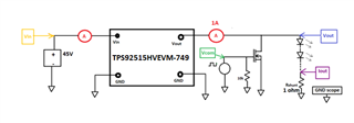
I’m designing a board to control some LED (12x, in series).

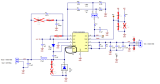
I’m using the TPS92515HV to do so.
I have used a transistor to short the LEDs as you did in your project "TIDA-01081, TIDRUT1".

Questions :

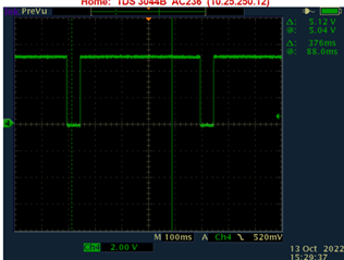
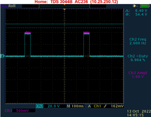
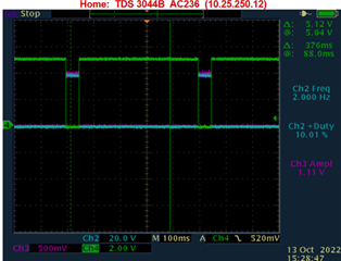
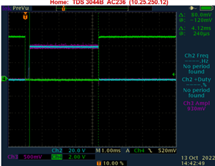
  1. What is the minimum pulse width one can do with this IC and do you have any associated waveforms ?
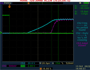
  2. Also there is a delay between the time I remove the short of the transistor and the time there is a current in the LED. Is that delay constant ?

If yes, what is its value ?

  • hi Richard

    1. do you mean the min. pulse width that should be applied on Q4 to properly turn on it?

    2. I think here your mentioned time delay should be the turn-off time of the transistor. While different transistors should have own values, for CSD18543Q3A, should be several nano seconds.

  • Hello Mason,

    1. Yes, of course. Can it accept 10us ?

    2. In fact, I have realized that there is always a delay between the time I trigger off the transistor Q4 and the time the current appears in the LEDs (x to 230us). This delay varies all the time. Why is it not constant and what is it minimum value ?

    Thanks,

    Richard

  • Please, kindly watch the video to see how the delay varie.

    Legend :

    Green signal : The Q4 trigger

    Blue signal : Voltage in the LED

    Purple signal : Current in the LED

    Thanks,

  • hi Richard

    would you mind sharing your schematic first? 

    so, the operation condition is: Vin=45V, VLED=?, ILED=1A, what is the dimming frequency of VCOM?

  • Hello Mason,

    Here is my circuit.

    Note I'm still testing the evaluation board. So the only addition circuit is my transistor and the 10k resistor.

    Green signal : The Q4 trigger

    Blue signal : Voltage in the LED

    Purple signal : Current in the LED

    Thanks,

    Richard

  • hello Richard

    thanks for the information. But do you mind sharing VLED (waveform shows ~40V, pls confirm ) and dimming frequency?

    Besides, can you also add SW together with original signals in both Q4 on period and Q4 off period. I would like to see the whole time period view. thanks

  • Hello Mason,
    I'm sorry for the delay. You asked it before, but I forgot.
    Here are the signals:

    Vin = 45V

    VLED = 34V (12 LEDs in series)

    VtriggerQ4max = 5V

    freq_triggerQ4 = 2Hz

    Duty cycle VgateQ4 =  90%

    So Duty cycle_VLED = 10% (since signal is inverted at the drain of Q4).

    (See messages above for the legend)

    Thanks,

  • Just to add that when you put all the curves together, you dont see the delay. It is whwn you zoom on the trigger time that you see the delay of the voltage and that of the current.

    Thanks,

    Richard

  • hello Richard

    thanks for the information. 

    as I mentioned, is it available to capture SW waveform together with other signals shown below?

    Besides, for shunt dimming, it is necessary to derive the OFF-time ramp from an alternate source. When the output is shunted, the output voltage becomes very low and possibly less than the 1 V OFF-timer threshold voltage. If this occurs, the off timer is not able to trip and the OFF-time reaches the maximum OFF-time before the switch is turned on again. this may cause some uncertainty when Q4 trigger on. more detailed information, pls refer to 8.3.4 in datasheet.

  • Hello Mason,
    Kindly find in the figure below, the signal VSW (in yellow).

    Thanks,

    Richard

  • hello Richard

    thanks for your information.

    According to the waveform above, when Q4 is triggered on, the SW is clamped to min. on time due to output voltage is shunted zero volt. This means during this period of time, inductor current is quite small and additional start-up time is needed when Q4 is triggered off and LED current rises. 

     I think add alternative source mentioned in last reply will help reduce start-up time as it will let inductor current still maintains in the target current value when Q4 is triggered on.