Because of the holidays, TI E2E™ design support forum responses will be delayed from Dec. 25 through Jan. 2. Thank you for your patience.

This thread has been locked.

If you have a related question, please click the "Ask a related question" button in the top right corner. The newly created question will be automatically linked to this question.

TPS61040: enable/disable to extend battery life

Part Number: TPS61040

I am trying to decide whether to periodically disable the TPS61040 to conserve battery life. The load on the switcher will be disconnected when not needed no matter what, so the comparison I'm trying to make is whether the switcher uses more energy (1) being left enabled for 50ms or (2) being disabled for 45ms and enabled for 5ms. The quiescent current is 28uA, so 28uA * 50ms = 1.4mA*ms. I captured the following waveform of the voltage across a 3.3-ohm resistor in series with the switcher input at startup:
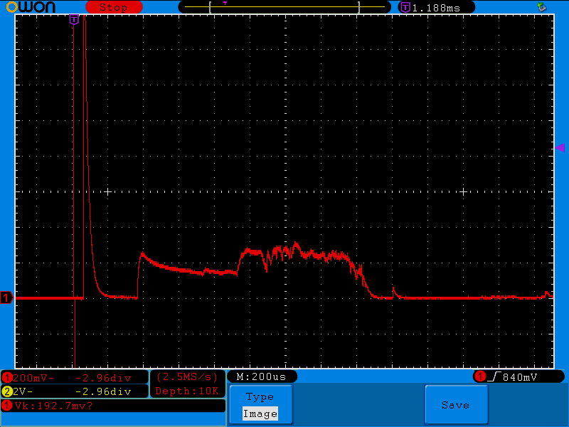
The average voltage looks to be about 200mV over a period of 2ms, which equates to a current of 200mV/3.3ohms, or 60.6mA. The startup energy is therefore 60.6mA * 2ms, or 121.2mA*ms. This is far more energy than would be spent just leaving the switcher running. I realize that having a resistor in series with the switcher input changes the behavior somewhat, but is this result in line with what you would expect? It seems to me that the only way it would be worth it to disable the switcher is if the disable period were much longer, say 5s instead of 50ms. I don't do a lot of design with batteries so I'm just looking for some general feedback on whether I'm thinking about this correctly. Thanks, -Pat

  • Hi Pat,

    I think it would be better that connecting a current probe in series with the input instead of a big resistor.

    And more, I think the enable time and disable time may take consideration of your load condition, because when the device is disabled, your load is only powered by output capacitor, VOUT will drop. Then you need to enable your system before the VOUT drop to lowest voltage the load requests. So if your load is always working, being disabled for a while would not save more energy because the device needs to charge output capacitor when being enabled again.

    If your load works for a while then stops, you can disabled the device to save more energy when load doesn't work.

    Best Regards,

    Nathan

  • Thanks for your advice Nathan. Unfortunately I don't have a current probe but I'm hoping that the 3.3-ohm series resistor will provide a reasonable measurement without affecting it too much. I may try some measurements using a lower value current sense resistor. As for the load, it will only be connected when the switcher is enabled so I don't have to worry about repeatedly charging the output capacitor.

  • Hi Pat, 

    Do you mean that your load doesn't have any requirements for the duration of power supply? I mean generally the load needs to work for a while and then stop, so the power supply also needs to satisfy this.  I am not sure about your load's operation mode or requirements.

    Regards,

    Nathan

  • Hi Nathan - all I was saying is that the load will not be connected when the switcher is not enabled, so there will be no voltage droop on the output capacitor. 

  • Hi Pat,

    If that, longer period which means fewer number of start-up should be fine.

    Regards,

    Nathan

  • Hi Pat,

    If that, longer period which means fewer numbers of start-up should be fine.

    Regards,

    Nathan

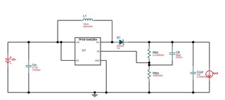
  • Thanks Nathan. My design actually requires that I perform a measurement every 50ms (the measurement circuitry is the load on the switcher, about 100uA). The measurement takes about 5ms. So I agree that only a much longer period (like 5s) would make enabling and disabling the switcher a good idea. Do you have any experience measuring the startup current of this device or one similar? I'm just wondering if what I'm seeing is roughly what should be expected. Again, it's about 60mA for 2ms. I have attached a schematic of my switcher circuit. As a reminder, I am measuring the startup current with no load connected to the switcher. 

  • Hi Pat,

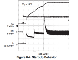
    I think it should be normal behavior. You can also take Figure8-4 (Start-up behavior) in datasheet as reference.

     The Il in this figure is inductor current.

    Regards,

    Nathan

  • Thanks for your help Nathan. I may try to measure the current with a lower series resistance or a current probe and I will report back if I do.