This thread has been locked.

If you have a related question, please click the "Ask a related question" button in the top right corner. The newly created question will be automatically linked to this question.

TPS5430: IBB for 12V in = +5V/-5V out @ 0.7A

Part Number: TPS5430
Other Parts Discussed in Thread: TPS62901, LMR33640, LMR33620

Hi Team,

I needed help with selecting the right product for 12V input, +5V/-5V out @ 0.7A IBB topology.

I would like to use two TPS5430 as a solution (one for +5V and another for -5V), however, I am not quite sure how to calculate the output current for IBB. Can you guide me?

Also, Is my product selection okay? or is TPS62901 better? OR do you have another product that better suits my requirements? 

Thank you in advance.

Regards,

Marvin

  • Hello

    I think that the TPS5430 would work in your IBB application.  I think that the current rating of that device

    is a little large for your output.  I think that the voltage rating of the TPS62901 might not be enough for your application.

    Please see the attached application note to help you determine the required current rating for your IBB.

    That will help you to decide what device is good for you.

    Thanks

    5736.snva856a.pdf

  • Hi Frank,

    Thank you for the response. I read through the document you provided (including slva317b and SLVA721A). However, I have trouble understanding the current calculation part. 

    On the snva856a there is an example that uses LMR33640, however, it is rated at 3A, if 1A is my requirement, what would be the changes I should do? (or do we have a converter that can convert + voltage to a - voltage directly?)

    I hope you can explain further. 

    Regards,

    Marvin

  • Hello

    In your case you would first calculate the inductor current assuming an efficiency of 0.85, from eq. 4.  That

    gives about 1A.  Then assuming 30% ripple you get 0.3A of ripple.  Using eq. 6 you get a peak of bout 1.2A, or so.

    So, you need a device with at least a current limit of 1.5A to be safe.  

    You can use the LMR33620 and the same circuit shown in the app note for the LMR33640 and change the inductor.  Or another device with 

    a 1.5A or 2A current rating.  The inductor size is calculated with eq. 8.

    A good way to test is to get one of the buck EVMs for the device you choose and configure as an IBB as shown

    in the app note.

    Thanks

  • Hi Frank,

    Thank you so much for the help. We have now progressed with the schematic and tried simulating using Pspice. However, I encountered an error. the pin 4 (PG) is having error if left floating. I checked the datasheet for the device and I found that of Pin 4 is not used. I can left it floating but the simulation model does not allow that. Can you help? Here is the file.

    LMR33640_TI.zip

    Also, can you check if the schematic and values are correct? Thank you kindly.

    Regards,

    Marvin

  • Hello

    Your calculations are correct.

    You can not hook up the simulation model as an IBB the way you have it.  The simulation model has

    internal ground connections that are global.

    You will need to hook up the model as shown in figure 8 of the application note SNVA856.

    You would hook up the input supply as shown in the figure.

    To avoid a floating node on PG, you can connect a resistor from the PG node to the GND pin of the model.

    Thanks

  • Hi Frank,

    I updated the schematic and the issue with the PG has been resolved. I checked the input supply against figure 8 but I am unable to find any difference? Would you kindly specify? 

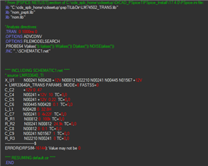
    I run the simulation using the updated schematic and got this:

    Thank you. 

    Regards,

    Marvin

  • Hello

    You need to start with a normal buck schematic with all the grounds in the normal place.

    Get the buck to work.

    Then just take the input supply and connect its negative terminal to the normal buck output.

    Thanks

  • Hi Frank,

    I did what you instructed but I still cannot get this to work. 

    There must be something I have done wrong in the schematic or simulation setup. Can you show me how its done? 

    5.zip

    Thank you.

    Regards,

    Marvin

  • Hello

    Let me re-assign this post to the engineer assigned to E2E for this month.

    He will be able to help you further.

    Thanks

  • Hello Marvin, 

    I made some modifications to the design you sent but was unable to get the model to simulate so this will need to be looked into more.

    In the meantime please download the LMR33640 model from the product folder, this includes an IBB schematic that can be simulated. 

    I've provided the zip file here: snvmbv0.zip

    Regards,

    Harrison Overturf