This thread has been locked.

If you have a related question, please click the "Ask a related question" button in the top right corner. The newly created question will be automatically linked to this question.

LM5164: Design of FB ripple

Part Number: LM5164
Other Parts Discussed in Thread: LM5017

Hi,

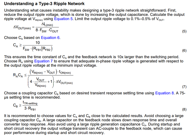
When I use LM5017, the following article is referenced to design FB ripple and Tpye 3 network is used. But I don't know how formula (8) and formula (10) in page 7 are derived and why CA and CB are designed like this.

https://www.ti.com/lit/an/snva776a/snva776a.pdf?ts=1666768598040&ref_url=https%253A%252F%252Fwww.ti.com%252Fsitesearch%252Fen-us%252Fdocs%252Funiversalsearch.tsp%253FlangPref%253Den-US%2526searchTerm%253DSelecting%2Ban%2BIdeal%2BRipple%2BGeneration%2BNetwork%2Bfor%2BYour%2BCOT%2BBuck%2BConverter%2526nr%253D82

Thanks

Regards,

Xun

  • Hi Xun,

    Please refer to below explanation.

    Thanks 

    Colin

  • Hi Colin,

    I'm afraid I stil couldn't understand how to get formula (6)(7)(8).

    In (6), I can't understand why the time constant is only related to RFB1//RFB2 and CA, but irrelavant to RA and CB?

    In (7), what the means of (4*VOUT/VIN(min)+1)?

    In (8), what factors influece tTR-settling? Since RFB1 is parralleled to RFB2 in small signal analysis, why tTR-settling is only related to RFB1?

    Could you please tell me the detailed derivation process of (6)(7)(8)?

    Thank you very much!

    Regards,

    Xun