This thread has been locked.

If you have a related question, please click the "Ask a related question" button in the top right corner. The newly created question will be automatically linked to this question.

TPS5430: Vout drop during start-up sequence

Part Number: TPS5430
Other Parts Discussed in Thread: TPS5450,

Gents,

I'm digging up this old post to follow up to new troubles.

At the time, the drops during stratup were fixed by reducing the COUT value.

Indeed the FCO, given  by   
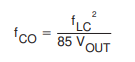
, limit wasn't repected (requirements >3kHz), with L=22µH and C=390µF ==> Fco = 2315Hz. 

By reducing Cout to 220µF ==> Fco became = 4104Hz. Experimental tests validated this solution.

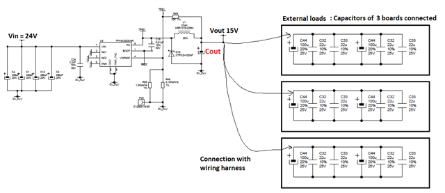
Below the schematic with capacitive load connnected (corresponding to the other boards)

Since a few months, the same starting problems have reappeared, without modification of any component. Boards are now in mass production.

These start-up problems occur "randomly", depending of board used. But for a faulty board the problem occurs at 70%. 

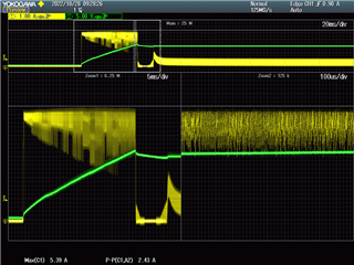
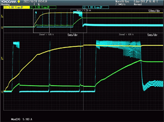
Below CH1: Vin (24V) / CH2: Vout (15V) / CH4: Lout current

I thought the problem was due to the current limitation of the TPS5430, so I tried to use a TPS5450. But Vout drop still present.

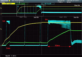
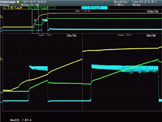
Below with the TPS5450 (Imax =7.5A)

CH1: Vin (24V) / CH2: Vout (15V) / CH4: Lout current

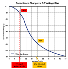
After lab investigations, it seems that the decoupling capacitor (front of TPS5430) have an impact regarding this trouble.

In our board design the input voltage is a +24V DCBUS, filtered with 4 alu caps (390µF/50V/40mR) and 2.2µF/50V/X7R close to the IC.

Does with capacitor repartition is OK with the datashet requirement ? See below:

So, I tried to increase the X7R capacitor value to 10µF. And yes, there is an improvement of the start-up sequence (problem occurs at 10%, instead of 70%).

But I did not see any difference in the shape of the voltage or current signals near the TPS5430...

To try to understand the phenomenon I made tests without decoupling capacitor (test by absurdity).

I you know what ? ==> No more start-up problems (100% of start-up sequences are compliant !)

So I'm a bit lost with all these tests and I need help with a new approach to understand these phenomena.

Thanks for your help, regards.

  • Hello,

    What is your load current during start-up? It looks like the device is hitting current limit. 

    Also, the inductor saturation current rating is 4.5A which is being exceeded in the images you are showing. The inductor may be saturating which is leading to the inductor current ramping up rapidly. Can you try testing with another inductor with a higher saturation current rating? Have you tried using the EVM to power the three external capacitive loads?  

    Regards,

    Harrison Overturf 

  • Hello Harrison,

    thanks for the replie.

    +15V loads during start-up are essencialy the capacitors (visible on pic above), a smart component (IGBT driver 2SC0435T) is also connected to the +15V but he does not consum current until supply > 7V, so he's it as considered inactive.

    I tried with different inductors:

    1- Same value 22µH and Isat=9A ==> Do not run !

    2- 33µH / Isat=6.5A ==> Do not run ! (idem with 44µH).

    3- 15µH / Isat=8A ==> Run !

    I also monitored the inductor current with hi resolution (1 sample per 1.6ns) and 50MHz bandwidth sensor, no shape of saturation is visible.

    what do you mean by : "using the EVM to power the three external capacitive loads ?"

    Many thanks.

    Regards 

    Fabien DENIS

  • Hi Fabien,

    Interesting that the same 22uH with a higher ISAT caused the device to not function. Are you sure it was soldered properly? 

    This is the EVM: TPS5430EVM-173 Evaluation board | TI.com 

    My question involves changing the resistor values of the EVM to yield 15Vout to see if the EVM can power the device or if it also runs into the same problem. 

    Are you able to disconnect the 3 external loads and test to see if the device can power up 1 at a time? If so does the same behavior still occur?

    Regards,

    Harrison Overturf 

  • Hi,

    Sorry for the delay, I'm back in the office today.

    For the test with the 22µH (Isat 9A), I am sure of the soldering.

    I have already tested the disconnection of external loads. Yes, it works (without load or with 2 loads).

    But in situ the 3 loads are connected.

    Please note:

    Sometimes it works with all 3 loads connected (with the initial configuration).

    The best actions for a good operation (with all 3 loads) are to reduce the choke value to 10µH or to increase the input decoupling capacitor to 10µF instead of 2.2µF.

    Thanks for the comments

    Regards,

    Fabien DENIS

  • Hi Fabien, 

    Thank you for sharing your observations regarding this design. If the design works with less load that leads me to believe that the device is hitting current limit at startup. It sounds like you are able to power up to 2 loads with one device, hopefully this is acceptable for your design. I'll close out this thread, but if you require further assistance with this topic please post a reply. 

    Regards,

    Harrison Overturf

  • Hi Harrison,

    Power up 2 loads is not acceptable for the final application (triphase inverter).

    What I need to understand is, why it works when

    1- The choke value is reduced to 10µH instead of 22µH (this action should favorize the current limit hitting).

    2- The input decoupling capacitor is increased to a 10µF instead of 2.2µF (no directe relation with current trip).

    I can modify the design with one of the two ideas (above), but I have to be sure why it works with.

    Many thanks for your help.

    Regards.

    Fabien DENIS

  • Hi Fabien, 

    Can you share an image of the proper start up sequence when the inductor is 10uH? Also, what is the part number of this inductor? 

    In terms of the input capacitors selected (the 10uF and the 2.2uF), what were these devices voltage ratings and RMS current ratings? When you removed the 2.2uF input capacitor initially and the design worked normally, perhaps this component was damaged due to violation of some of its ratings. 

    Also, I went back to the original post, did you ever try connecting EN to VIN through a resistor divider? 

    Regards,

    Harrison Overturf 

  • Hi Harrison,

    See below the test with the 10µH choke (ref : ETQP4M100KVCCH1: Lout current / CH2: Vout (15V) 

    As you can see the max current reach 5.39A, this is upper the trip value on the 1st screenshot (5.183A)

    Note, these comparative tests have been made with the same board and the same TPS5430.

    About the input capacitors, the 2 are 50V rating and the RMS current rating is > 5A @ 500kHz.

    Below the value change vs DC voltage applied. FYI, for the first trip the input voltage is equal to 9V 

    Tests with the 2.2µF removed, have been verified by a retest (new 2.2µF soldered and again removed).

    Yes, I have tested with the resistor divider between the VIN and EN pins, to delay the start-up of the TPS5430 when the input voltage is stabilized at 24V. There is no improvement on the start-up triggering behaviour.

    This is also visible in the first screenshot. The hiccup mode remains engaged even if the input voltage has reached +24V.

    Regards.

    Fabien.

  • Hi Fabien,

    Thanks for sharing this, have you been able to take thermal measurements? I want to confirm that the part's thermal protection is not being tripped. 

    What is the maximum output voltage level seen here:

    I would like to confirm if the part is triggering overvoltage protection here. Or is this event triggered by a change at the load side? 

    Regards,

    Harrison Overturf 

  • Hi Harrison,

    From my point of view, there is no thermal protection trip, all these tests were done in our laboratory (25°C) and 10 sec between each start to ensure the voltage drop of all the capacitors.

    On the screen, the maximum voltage is 16V, which is 1V more than the set point. Does this little overshoot is ok ? I think yes, please confirm.

    The change of load is due to the capacitors are fully charged.

    Regards,

    Fabien DENIS

  • Hi Fabien, 

    From a thermal perspective, the part is delivering a large amount of power right before the output voltage drops (in the snipped I sent before the output power is nearly 60W). Assuming RThetaJA=42.3C/W and using the minimum junction temperature for thermal shutdown (135C) the part would only need to dissipate 2.6W before hitting thermal shutdown. 

    Overvoltage protection is activated when voltage on VSENSE reaches 112.5% x VREF. Assuming the reference voltage is at the minimum 1.202V then the overvoltage protection circuitry could be activated if the output voltage reaches 16.65V. I want to confirm that this wasn't violating the overvoltage protection.   

    Can you send me images of the steady state waveforms (PH, VOUT, IL)? I'd like to see if there are any signs of instability. 

    Also do you have the ability to run a frequency response or load transient while the part is in steady state? 

    Regards,

    Harrison Overturf 

  • Hi Harrison,

    You talk about a case which working ? How do you calculate the output power in this case ? 60W seems to be huge.

    I dont think that it is a thermal trip, indeed the trip at start-up occur when the device is cold and the first trip occur after 5ms. After 6 hiccups (120ms) a new startup sequence is succesful and run 30ms. see below.

    Overvoltage protection may occur without that a hiccup mode is activated. There is no relation with the stratup trip, isn't it ?

    I'm not able to run a frequency response, I don't have the material for. 

    I'll sent on next monday the steady state and load transient waveforms

    Regards

    Fabien DENIS

  • Hi Fabien,

    I calculated output power by VOUT*IOUT=POUT. In the image below the output voltage is ~15V and the average output current is around 4A:

    I took another look at this image:

    During the first portion where the output voltage begins to ramp up prior to the device entering hiccup mode I calculated the required capacitance to produce this waveform:

    i=C(dV/dT)

    where

    i = 4.5A (this approximation is on the conservative side, it's likely a little higher)

    dV=4V

    dT=4msec

    Solving for C = 4.5mF! This approximation assumes a purely capacitive load with no other load pulling current from the output. If this is the case then this calculated output capacitance is much higher than what is shown in your schematic. Can you confirm that there is not some other load pulling current from the 15V rail when the device is turning on? Is it possible to completely disconnect all other loads besides the capacitive load? 

    I look forward to the steady state images on Monday. 

    Regards,

    Harrison Overturf