Because of the holidays, TI E2E™ design support forum responses will be delayed from Dec. 25 through Jan. 2. Thank you for your patience.

This thread has been locked.

If you have a related question, please click the "Ask a related question" button in the top right corner. The newly created question will be automatically linked to this question.

TPS746EVM-009: Startup time

Part Number: TPS746EVM-009
Other Parts Discussed in Thread: TPS785-Q1

Hi,

A issue about the startup time of TPS746EVM-009 that we need your comments:

1. Without any load, the startup time of the EVM is quite small;
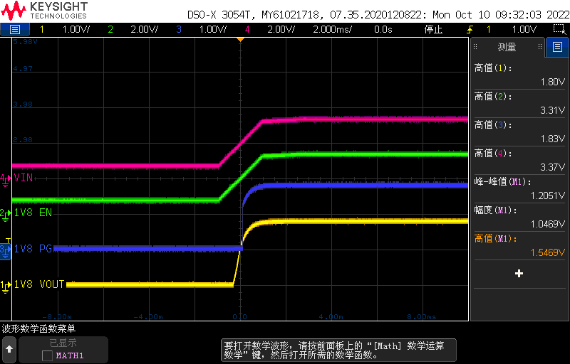
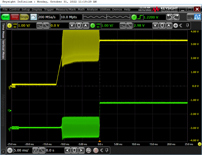
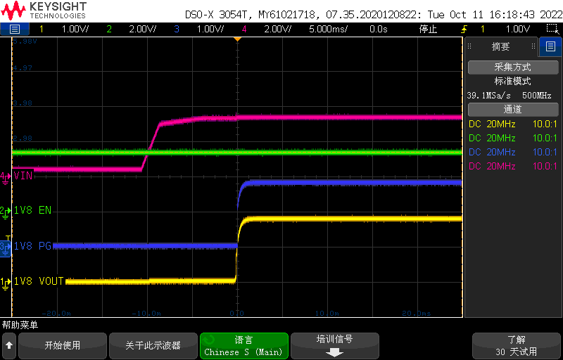
2. With 10mA load, the startup time is about 10ms;
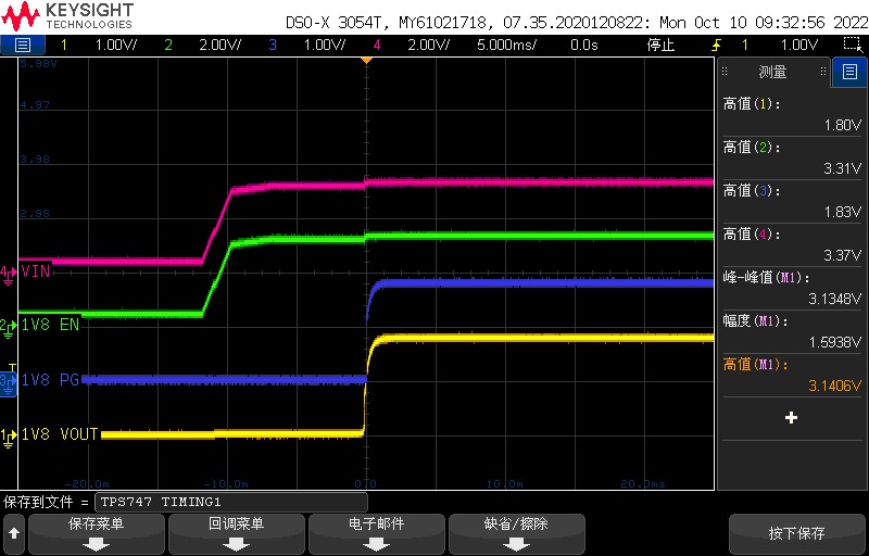
3. When the load is 200mA, the startup time increased to 17ms;
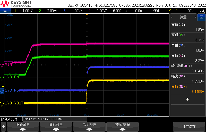
It seems that the startup time of the chip will be infulenced by its load, this is inconsistent with its specification(500us).

We need your help to analyse the test data and want to know whether there is a way to reduce the startup time.

Test condition: VIN = 3.3V; VOUT = 1.8V.


  • Hi Chen,

    We will get back to you in 1-2 business days, thank you for your patience.

    Regards,

    John

  • Hi Chen, 

    Does this set-up use a FF capacitor?

    https://www.ti.com/lit/an/sbva042/sbva042.pdf?

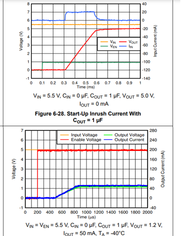
    500us is the typical start-up time:

    when under these conditions:

    also, because the current is larger, the LDO follows a similar turn on rate. You can try decreasing the output capacitors based on the requirements of your application. 

    Best,

    Juliette

  • Hi Juliette,

    Thanks for the feedback!

    Following the test conditions you attached, I re-tested the EVM:

     VIN = 3V3, VOUT = 1V8, IOUT = 1mA, VEN = VIN, CIN = COUT = 1uF and removed CFF.

    Which has no significant difference with the result I tested before:

     VIN = 3V3, VOUT = 1V8, IOUT = 1mA, VEN = VIN, CIN = COUT = 2.2uF and CFF = 0.01uF.

    Seems CIN/COUT/CFF are not the root cause. Is there anything else that I could try?

  • Hey Chen, 

    Is the EN signal distorted before VOUT goes high because of a probe connection issue?

    Is the output load a resistive or electronic load?

    I think the internal soft start of this part is limiting the output of the device.

    This white paper may be able to explain better, but the delay time is affected by the soft start circuitry, resistor divider and output load. 

    /cfs-file/__key/communityserver-discussions-components-files/196/1616.Soft_2D00_Start-Circuits-for-LDO-Linear-Regulators_5F00_slyt096_5B00_1_5D00_.pdf

    The TPS785-Q1 also has an internal soft-start and the delay between enable and output also increases with IOUT:

    We can try reducing R1 to increase the current going into the FB pin to see if this changes the delay time, but I am not sure it will. 

    After speaking with some colleagues they think the part is simply damaged. Does this problem persist when the part is replaced?

    Best,

    Juliette

  • Hi Juliette,

    Thanks for your reminder!

    The former results were based on constant current electronic load, and after change the load to a resistive one, the results could meet the specification defined in the datasheet. For EN signal, we just want to see whether put the EN signal high before VIN is given will bring any difference.

    In addition, why the LDO regulator has a much more startup time with constant current load than the resistive load?

    Xuelong

  • Hey Xuelong, 

    We don't usually recommend that VEN go high before VIN goes high - we typically recommend that VEN be tied to VIN if that capability is undesired. 

    For this device it does not seem like it would cause any damage; however, using enable after VIN can help avoid issues on start-up:

    Eloads tend to interact with the internal control loop of the LDO. For steady state tests, eloads can be used; however, we use resistive loads for consistency/ to avoid errors that come from eloads. 

    Best,

    Juliette

  • Got it.

    Thank you so much, Juliette!