This thread has been locked.

If you have a related question, please click the "Ask a related question" button in the top right corner. The newly created question will be automatically linked to this question.

TPS23758: Strange behavior of internal startup current source

Part Number: TPS23758
Other Parts Discussed in Thread: , TPS23755

Hello,

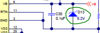
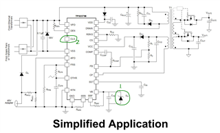
we are using TPS23758 on a POE board which is based on TI TPS23758EVM-080 Evaluation Module. Part behaves well for the most part, but we have noticed a strange problem on some of the PCBs. For a very small number of boards TPS23758 doesn't start up correctly. There is always 48V input present so it seems handshaking sequence goes through ok, but the Vcc internal startup current source doesn't reach 11V needed to power the IC electronics. This means there is no switching, and no output voltage.

First two pictures show Vcc voltage during startup, and other picture is Vdd during startup. Vdd seems fine, but Vcc starts oscillating at around 3.2kHz.

Do you have an idea what could be causing this, or any suggestions what to check? There doesn't seem to be a short circuit or anything heating up. 

Best regards,

Becir

  • Hi Becir,

    Thanks for reaching out to us! 

    Could you send us your schematic of the PoE part? 

    For TPS23758 especially, could you check if you have a Zener diode between VB and RTN. We used to have overshoot issue caused at VB, so we have a 6.2-V Zener diode to make its max voltage less than 6.5-V rated value. And it is also shown in TPS23758EVM-080.

    Best regards,

    Diang

  • Hello, 

    I can't share the schematic here, but I can say that we don't have Zener diode connected there. Is it required to prevent the issue, or the diode can limit voltage on Vcc?

  • Hi Becir,

    Thanks for your information. The Zener diode is required here to prevent the VB overshoot during PoE turning off if the class resistor is not open.

    We saw VB spike, which could exceed VB's 6.5-V limitation, for TPS23755 & TPS23758 without open class resistor or Zener diode. Please see the 2 solutions below, and either one could prevent VB get damaged:

    1. Add a 6.2-V Zener diode between VB-RTN to clamp the VB spike;

    2. Leave the CLS pin open to configure the PD to Class-0, which is up to 13-W PD input power.

     Power level

    RCLS

    VB Zener (6.2V)

    Class0 (13W)

    OPEN

    No

    Class1 (3.8W)

    121Ω

    Yes

    Class2 (6.5W)

    68.1Ω

    Yes

    Class3 (13W)

    OPEN

    No

    Best regards,

    Diang

  • Thank you for the suggestions, I will try both solutions and get back to you.

    Best regards,

    Becir

  • Hi Becir,

    Thanks for your fast reply!

    This Vcc behavior and startup failure shown from you could imply that the TPS23758 was damaged.

    Either two of these solutions can help to prevent a new chip to have VB failure but they may not help to fix a damaged chip. 

    Best regards,

    Diang

  • Thank you for your feedback. We will discuss internally and see which solution suits us best.

    Best regards,

    Becir