Good evening,
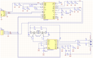
I'm using the BQ28Z610 on this battery-management circuit with 2x 18650 batteries:

I tried using a FET+OP AMP circuit for providing constant current for the Learning Cycle, but something is not working right. After I perform the Learning Cycle and then place this battery-management board on my final device, it charges up to 100% (showing on my final device's screen) with no problem. But then as I use my final device, when it discharges the batteries down to ~30%, the percentage drops to 0% and stays at 0% for a long time, still working. Until this battery-management board finally cuts battery power down, keeping it cut until the battery is recharged again by plugging the USB charger on this board-management board.
I looked all over TI Reference Designs library but couldn't find anything for this task.
I've seen posts of people that used voltage regulators for providing constant current, but I'd like to know:
1) What's the most common or recommended way to draining/providing constant current for the Learning Cycle and Chemistry ID Matching?
2) Are there TI products specific for this task: the Learning Cycle, and even Chemistry ID Matching?
Thanks in advance!


