This thread has been locked.

If you have a related question, please click the "Ask a related question" button in the top right corner. The newly created question will be automatically linked to this question.

TPS54561: supports a switching frequency range of 100 kHz to 2.5 MHz

Part Number: TPS54561

HI TI

The switching frequency of the TPS54561 is adjustable over a wide range from 100 kHz to 2500 kHz by placing a resistor between the RT/CLK pin and GND pin.

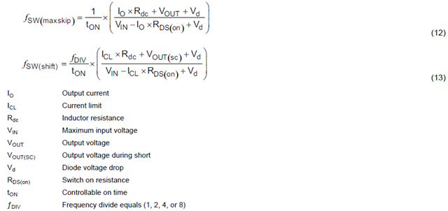
However, according to the application example in the datasheet (8.2.1 Buck Converter for 7-V to 60-V Input to 5-V at 5-A Output), the switching frequency cannot be higher than 708 kHz and 855 kHz which are calculated from equations 12 and 13, so the switching frequency 400 kHz was chosen for this application example.


My question is, taking TPS54561 device as an example, the maximum switching frequency of 2500 kHz can only be supported in specific operating conditions, not in all operating conditions?

  • Hi Kingson,

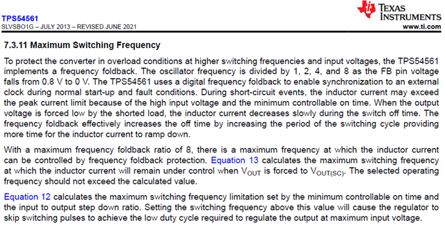
    Yes the maximum FSW of 2500 kHz can only be supported in specific operating conditions. According to the datasheet for TPS54561, the maximum frequency is limited in overload conditions such as high input voltage. The converter will implement a frequency foldback in such a case where the frequency is reduced by a ratio. See section 7.3.11 below.

    Regards,

    Henry

  • Hi Henry

    Thanks for your replying.

    For the application example in the datasheet (8.2.1 Buck Converter for 7-V to 60-V Input to 5-V at 5-A Output), the switching frequency should not large than 708kHz and 855kHz according to equation 28 and 29.

    What can we do if we want a higher fsw of 1.0MHz? Or, could you give me a example TPS54561 Buck Converter for 7-V to 60-V Input to 5-V at 5-A Output with fsw=1.0MHz?

  • Hi Kingson,

    Typically frequency foldback will be an issue during VIN line transients where the input will rise, temporarily putting the IC into frequency foldback. However in most cases, depending on your max nominal VIN, max nominal load current, and inductor resistance, I believe you can design your system to have a nominal FSW of 1MHz. Then, if the line transient occurs, frequency foldback happens temporarily, but then converges back to operation at 1MHz. If you'd like, I can go through the calculations using eq. 12, 13 if you could give me the max nominal VIN, max nominal load current, and Inductor model number.

    Regards,

    Henry

  • Hi Henry

    This is our TPS54561 Design Requirement with Switching Frequency 1.0MHz:

    Input Voltage Range: typ 12 V, from 7.0 V(Vin(min)) to 60 V(Vin(max))
    Maximum output current: Iout(max) = 5.0 A
    Current Ripple Factor 0.3
    Output Voltage Vout = 5.0 V
    Operation frequency 1.0MHz

    1. Output voltage setting
    Vout=0.8*(1+53.6/10.2)=5.00V


    2. Output Inductor Selection (LO)
    LO(min)=(60V-5.0V)*5.0V/(0.3*5.0A*1.0MHz*60V)=3.06uH => 3.3uH will be selected.
    Inductor RMS current ≈ 5A
    Inductor peak current, Ipeak = (1+0.3/2)*5.0A=5.75A or Ipeak =5.0A+(60V-5.0V)*5.0V/(3.3uH*1.0MHz*60V)=5.69A
    WE 74437349033(29.9 mΩ max), Bourns SRP6540-3R3M(23 mΩ max) and Pulse P1168.332NL(11 mΩ max) can be used.
    Due to low Rdc, Pulse P1168.332NL(11 mΩ max, rated current 6.4A, Saturation current 7.3A, 3.3uH) will be selected.

    3. Selecting the Switching Frequency
    But, according to the calculation result of tps54561 datasheet eq28 and eq29, the switching frequency can not larger than 708kHz and 855kHz.

    What we can do if we want to avoid the frequency foldback?

    Thanks,

    Kingson.

  • Hi Kingson,

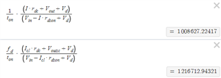
    Thanks for the information. Based on those values and Eq. 12 and 13, I've calculated that you need a max VIN of 42V to avoid your frequency dropping below 1MHz. See calculations below. It seems like your continuous VIN is 12V, so it should operate at 1MHz Fsw. If your VIN transient exceeds 42V, frequency foldback will occur for only the duration of the transient which should be several milliseconds at most. 


    For VIN = 42V, I = 5A, t_on = 135ns, r_dc = 11mΩ, VOUT = 5V, Vd = 0.7V, Rds_on = 87mΩ, Fd = 8, I_cl = 6A, Vout_sc = 0.1V.

    Regards,

    Henry

  • Hi Henry

    Well done. you have solved the problem above.

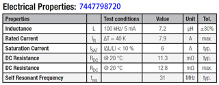
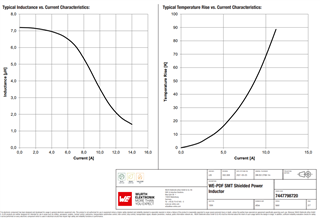
    One more question: in the chaper 8.2.1.2.3 Output Inductor Selection (LO) of tps54561 datasheet, "The chosen inductor is a WE 7447798720, which has a saturation current rating of 7.9 A and an RMS current rating of 6 A."

    But, from the 7447798720 datasheet(as below), 7.9A should be the Rated Current and 6A should be the Saturation Current.

    Is there a confusion with Rated Current and Saturation Current of 7447798720 in the TPS54561 datasheet?

    Thanks.

  • Hi Kingson,

    It might seem like there is a discrepancy between rated RMS and saturation current in our datasheets, but let me explain.

    According to Wurth and Coilcraft, the definition of saturation current is the DC current level where inductance drops a specified amount. In addition, RMS rated current is defined by the current where temperature rises a specified amount. So there is a bit of arbitrary specification here that can be further examined by looking at the following graphs in the inductor datasheet.

    According to Wurth, they have a 10% inductance drop for saturation current at 6A, while our datasheet went with around a 25% inductance drop at 7.9A. For RMS rated current, Wurth have a 40K temperature rise for 7.9A, while our datasheet has a 20K rise at 6A which is more reasonable for our solution. We chose this inductor because these graphs work with our application. Yes, the terms saturation and rated RMS currents may seem vague, but I strongly recommend looking at the graphs to make sure. Often times the table on the front page takes advantage of the vagueness for marketing purposes.

    Regards,

    Henry

  • Hi Henry

    Usually, for example, the data you write to the TPS54561 datasheet is not directly referenced from WE 7447798720 datasheet, but is written into the TPS54561 datasheet based on the measured results of WE 7447798720?

  • Hi Kingson,

    The approach we always use is to look at all the data in the datasheet, and then choose the inductor which best works with our applications based on measured data.

    Regards,

    Henry

  • Hi Henry

    Thank you very much for your patience.