This thread has been locked.

If you have a related question, please click the "Ask a related question" button in the top right corner. The newly created question will be automatically linked to this question.

LM5118: Buck-boost design, low efficiency at low Vin high loading condition

Part Number: LM5118

Hi TI experts,

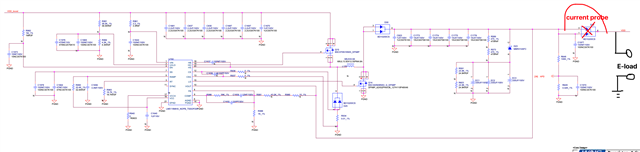
We have a LM5118 buck-boost design with below spec.
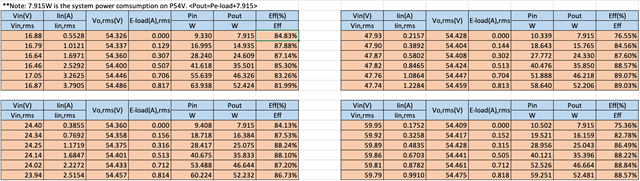
Vin: 16V-68V

Vout: 54V

Iout-max: 1A

We observed low efficiency when Vin is 16V and 24V, while the Iout is close to 1A. The measured efficiency is only 65% at 16Vin/1AIout and 74% at 24Vin/1AIout. 

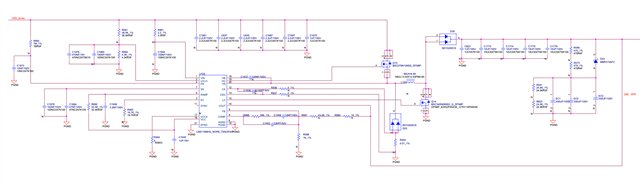
Could you review the schematic and advise how can the efficiency be improved?

Thanks,

Neo

  • Hi Neo,

    thank you for using the E2E forum.

    I assume the efficiency goes down gradually. Do you have some more data points also at the levels above? Or where does is start to get less efficient?

    First it would be good to find out which component is contributing to this loss.

    Can you try to find out which component is contributing to the loss? This should be measurable by a temperature increase.

    You can also check the voltage drop across the MOSFETs with differential probe?

    Best regards,

     Stefan

  • Hi Stefan,

    There should be some test setup issue with original test data. The updated efficiency is as below, which looks pretty good.

    However, when P54V output current is monitored by current probe, the current waveform is swinging like sine wave. Even with e-load current added, it still looks like sine wave with higher amplitude. Is this reasonable or not? 

    24Vin, P54V output current, 0A-eload

    24Vin, P54V output current, 0.5A-eload

    Here is where the current is measured and e-load added.

    Thanks

    Neo

  • Hi Neo,

    Thank you for the update.

    When going through the new questions I do not understand the first point:

    "24Vin, P54V output current, 0A-eload"

    -> How can there be any current oscillation with no current

    Another point to check:

    Can you check the output voltage with a scope probe. If this is stable and the eload should give a constant load, something with the eload or the current probe is not OK.

    Best regards,

     Stefan

  • Hi Stefan,

    Please find my update.

    "24Vin, P54V output current, 0A-eload"

    -> How can there be any current oscillation with no current

    --> The system loading is about 7.9W. The current waveform is the system current (e-load connected in parallel with system but set as 0A)

    Another point to check:

    Can you check the output voltage with a scope probe. If this is stable and the eload should give a constant load, something with the eload or the current probe is not OK.

    --> The output voltage is stable, the switching node waveform looks ok. I can provide the output voltage after capture it.

    With current probed on e-load only, it looks constant at ligh load (<0.5A) but goes to swing gradually after e-load increase.

    i will double check the current probe and e-load.

    Meanwhile, if you have any other comments, please kindly let me know.

    Thanks

    Shisong

  • Hi Neo,

    as mentioned, if the output voltage is stable (keep in mind we do voltage regulation) the issue is needs to be the eload side.

    May you can try another one or use a shunt resistor as load to check.

    Best regards,

     Stefan

  • Hi Neo,

    I have not seen up update on this thread for 11 days.

    So, I assume the issue is solved and i will close this thread.

    In case there is still something open, just reply to reopen or start a new thread.

    Best regards,

     Stefan