Hello,
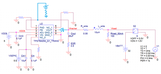
I am simulating with tracker TPS7B4254-Q1, and I have some questions, but first of all, let me clarify about you can see in the schematic in PSPICE:
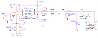
- I had to place high impedance resistors at NC and PAD pins to avoid errors.
- I am simulating a shortcut to battery (32V) .
- Input to tracker is an internal power source of 5.5V.
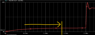
- ESR is there to decrease high voltage oscillations at pin 5 (Vout), in principle this could be an option, but other impacts would need to be analyzed.
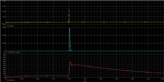
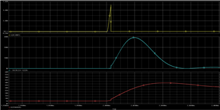
And these are the results:
My questions are:
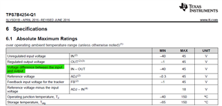
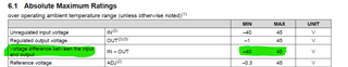
1.- According to specs, maximum operating voltage at VOUT is 40V, so, I am assuming that in this particular situation (shortcut to battery - SCB) , device is able to survive to this voltage peak, is this right?, actually this condition is also met:
2.- Looking at the input current in VOUT pin during this SCB, you can see a peak about 5A - entering to the device -, I do not find specifications in this regards, is the device able to withstand this current peak?
3.- Is the output settling time shown something expected, around 1.4ms ?
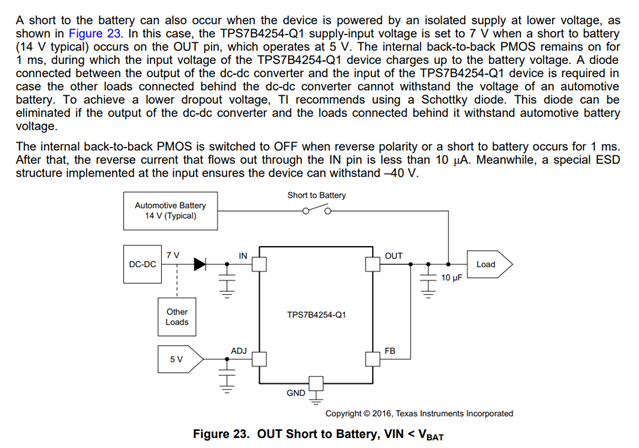
4.- is this protection method compatible with the device: ?
Thank you.