A related question is a question created from another question. When the related question is created, it will be automatically linked to the original question.
If you have a related question, please click the "Ask a related question" button in the top right corner. The newly created question will be automatically linked to this question.
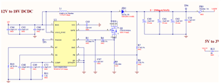
1. The Vin is 12V and Vo is 18V !!! (It's mean 12V boost to 18V)
2. What is 4. referring too ? I might miss the history.
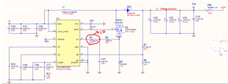
--> No history here , the below SCH have changed some parameter value of the element now .(The change is "R5 change to 10ohm" But the SCH has not changed yet)
- Inductor might be too small from the current rating, peak inductor current is 5.24 A. Please consider this (plus some margin) for saturation current rating of the inductor. Wenn considering the max current limited by the sense resistor the peak current can go up to 10A)
- compensation and loop stability does not look OK. Changing R11 to 2.5k looks much better
You can also check this with the Quickstart calculator which can be found on the product page.
Do you know which software for the PCB has been used - just tried Altium but it was not able to open the file?
Check for Thermals pads also the other part of the layout, this can have a quite negative impact on power design as it reduces the current path to thin wires.
I have not seen an update for the last 14 days, so I assume the questions are/or answered and the issue is solved. I close this thread now. If there is still something open reply and the thread will get open again. If you have any other question or of the thread gets locked, please open a new one.
Clicking the Resolved Button also helps us to maintain this forum.