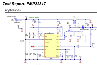
Other Parts Discussed in Thread: PMP22817
I'm designing a 12V-24V SEPIC using LM51561-Q1 controller following the SEPIC excel sheet calculator.
I understand since the D>50%, special care should be giver for current reference slope compensation.
I followed the values calculated in the excel sheet calculator but the results from simulation always show undamped oscillations in inductor currents in steady state.
I even simulated the SEPIC in the PMP22817 reference design, and the simulation result (pdf attached) also shows oscillatory average inductor currents.
Is this behaviour related to the simulation or the values calculated for COMP network?


