This thread has been locked.
If you have a related question, please click the "Ask a related question" button in the top right corner. The newly created question will be automatically linked to this question.
Dear Team,
Good Day..!!!
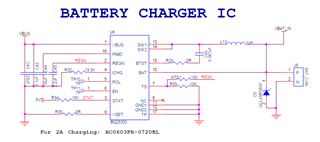
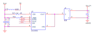
Please verify the attached Battery Charger IC schematics and let me know feedback on the same. We are developing a Ultra low current measurements board to measure the Nano current and device is battery powered device so we used BQ25303 Battery charger IC and it charge by Type C cable.
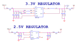
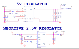
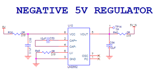
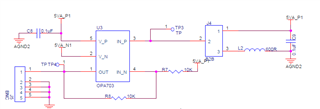
And I have one more query, in this design I have used ADC AD7173 and DAC DAC8550 which needs Negative power supply rails, so from Battery Power I have converted the necessary power rails. Attached Power circuit for your reference please check and let us know your feedback either it is good recommendation to step up and step downing with multiple regulator's
From DAC output have connected one Op Amp to make it as Bi-Polar Logic based on the DAC8550 Reference, please do review the same
Kindly review and let us know your feedback for the above.
Thanks
Sagar
Hello Sagar,
My schematic review for the BQ25303J is as follows:
1. We recommend only 2.2 uF on VBUS. I see 22 uF attached.
2. You have set the maximum battery charging current of 3.0 A.
3. Confirming 4.2 V charge regulation.
4. 10 uF is recommended on the BAT pin. I see this is met by all the regulator input capacitance. However 10 uF needs to be placed by the inductor output as shown in the Pin Description.
5. As shown in 10.2.1.2.3 Inductor Selection, "Inductance value is selected based on maximum input voltage VVBUS_MAX in applications. 1-µH inductor is recommended if VVBUS_MAX < 6.2V and 2.2-µH inductor is recommended if VVBUS_MAX > 6.2V." Please choose according to your application.
My focus is on the battery charger and I cannot comment on the overall design in general. However, please use the right amount of decoupling capacitor for each regulator. In addition, make sure you layout properly to avoid noise issues. You have multiple switch-mode converters and the noise needs to be taken into account. Last, make sure you test and design for your typical and maximum load pull from the battery to make sure your overall design can handle it. For the DAC8550 you can open another thread and the right person will get back to you.
Regards,
Mike Emanuel
Dear Mike,
Thank you for the comments, Noted to according to your review points.
It would be helpful if you can suggest me a single PMIC so that it boost, buck as well as inverting power rails.
Thanks
Sagar
Hello Sagar,
You are welcome. Unfortunately I do not work for the PMIC team. Please open a thread with their team. Here is their product page: https://www.ti.com/power-management/multi-channel-ics-pmic/products.html.
Regards,
Mike Emanuel