


Other Parts Discussed in Thread: BQ25300, BQ25306
Hi.
Please, could this be revised by an engineer of Texas Instruments?
I'm open for tips and suggestions.
The initial schematic is attached.
DESIGN
Input voltage: 5.25V max, 4.75V min (5V +- 5%, input voltage is 5V typ)
Charge current (typ): 2.5A
Battery nominal voltage: 3.7V (Li-ion)
Battery floating voltage: 4.2V
Temperature protection: yes, using thermistor 103AT-2 from Semitec
SAFETY TIMER
Fast charge safety timer = 15h min, 20h typ, 24h max, shown at the end of page 10 of datasheet. 15h * 2.5A * 0.9 = 33.75. Ok, we will use a battery/polymer with a maximum of 20Ah capacity, in the worst case. If later we reduce the charge current to 2A, 15h * 2A * 0.9 = 27, it's also ok.
PIN VSET
Pin VSET is connected to GND using a jumper resistor, which sets the floating voltage of the battery to be 4.2V.
CHARGE CURRENT
Charge current of 2.5A
I_chg (A) = K_ichg (Aohms) / R_ichg.
K_ichg is typically 40000 Aohms
R_ichg= K_ichg / I_chg
R_ichg= 40000 / 2.5 = 16K ohms
R_ichg commercial = 15.8K ohms
Ichg (typ) = 40000 / 15800 = 2.53A
INDUCTOR SELECTION
The Inductor chosen has 1uH, because VBUS (Vin) is < 6.2V) [page 22 of the datasheet]. It is considered a maximum input voltage of 5.5V.
The inductor ripple current IRIPPLE depends on the input voltage (VVBUS), the duty cycle (D = VBAT/VVBUS), the switching frequency (fS) and the inductance (L).
The maximum inductor ripple current occurs when the duty cycle (D) is 0.5 or approximately 0.5.
I_ripple = ( Vin * D * (1-D) ) / (fs * L)
Iripple = ( 5.5 * 0.5 * (1-0.5) ) / (1.2*10^6 * 1*10^-6) = 1.14A
I_sat = Ichg + 0.5*Iripple
I_sat = 2.53 + 1.14 = 3.67A
Inductor chosen: Inductor microHenry, SMD, 1uH, +-20%, 5.8A current rating, 8.5A saturation current, shielded, 26mOhm max, -40°C ~ 125°C, 4.2 x 4.2 x 2mm, PA4332.102NLT (Pulse Electronics)
BATTERY TEMPERATURE PROTECTION
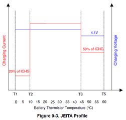
In the schematic it was used the values shown in the datasheet in page 17, that is, RT1 = 4.32K and RT2 = 21K. This charger IC, BQ25303J, uses the JEITA profile, picture below.
I have questions.
(1) Is it possible for the battery to be charged only between 0°C and 45°C? With 100% of ICHG, but only within this temperature range?
(2) Is it not dangerous to charge a battery between 45°C and 60°C with 50% of ICHG and with a maximum of 4.1V? Is this safe? I ask because this is the first time I'm working with a battery charger that monitors the temperature of the battery, and also the first time I knew about this profile called JEITA. And most standard Li-ion batteries are rated to recharge between 0°C and 45°C.
Regards,
Jeferson.
