This thread has been locked.

If you have a related question, please click the "Ask a related question" button in the top right corner. The newly created question will be automatically linked to this question.

TPS7B81-Q1: KVU(R-PSFM-5) PCB soldering information

Part Number: TPS7B81-Q1

Hi Team,

Does the package have the information like 

https://www.ti.com/lit/an/slua271b/slua271b.pdf?ts=1668084145183&ref_url=https%253A%252F%252Fwww.google.com%252F (Thermal PAD)

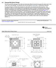
We want to know section 4.4 information about KVU(R-PSFM-5).

Regards,

Roy

  • Hi Roy, 

    I believe this is included in our DS, let me know if this is the information you are looking for: 

    In addition, there is section 8.1.1, that talks about power dissipation and the impact of PCB: 

    Lastly, here is a layout example from a similar device in KVU package: 

    Best, 

    Edgar Acosta

  • Hi Edgar,

    Thanks for information. But I can't find our suggestion in datasheet about solder-paste coverage of the pad area. 
    In addition, we also need the amount of voiding post reflow in the thermal pad solder joint (to be verified using an x-ray). 

    Regards,

    Roy

  • Hi Roy, 

    I'm a bit confused when you say you cannot find the suggestion in our data sheet, the screenshots shown come straight from the TPS7B81-Q1 Data Sheet, and it should be located almost towards the end of the DS (page 31 out of 36).

    Furthermore, when looking at the Land Pattern data, it shows the stencil design with the stencil openings and a 63% solder coverage on the exposed pad.

    When looking at section 4.4 of the App Note you shared: 

    This is essentially the same information as the one provided in the Data Sheet. 

    I will reach out to the Packaging Team in regards the voiding post reflow for the KVU package and see if the 50% limit still applies as well as described on the App Note.

    Best, 

    Edgar Acosta