This thread has been locked.

If you have a related question, please click the "Ask a related question" button in the top right corner. The newly created question will be automatically linked to this question.

LM5181: Questions on Device Operation and Fault Response

Part Number: LM5181

Hi team,

Could you please help advise - 

  1. What is the softstart reference voltage? 0.8V? Customer need to measure the softstart time at SS pin. 
  2. What is the switching frequency during softstart and how does it change? 
  3. "A failsafe current limit set at 1.2 A, or 1.6 times the nominal peak current limit, provides redundant fault protection in case of transformer short circuit or saturation effects." ==> how can customer test the 1.2A current limit? The current test result shows current limit at 0.75A. 
  4. In datasheet, there are VCC wordings in page 12 and page 15 - are they just typo and should be BIAS? 
  5. How to test UVLO threshold for BIAS?
  6. Thermal shutdown - is there any waveform or test result on thermal shutdown? 
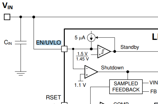
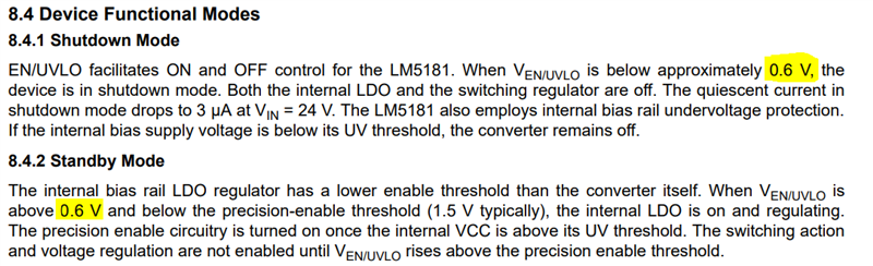
  7. What is shutdown level at EN/UVLO pin? 1.1V or 0.6V? There are multiple places stating this threshold in datasheet, some are 1.1V and some are 0.6V. 
  • HI PY

    1. SS is 1V, but pls notice that SS is control COMP voltage instead of FB
    2. As it control COMP so it will work at PFM before 0.7V, then it will come to DCM mode with 350Khz frequency 
    3. Using low saturation current transformer, let its saturation current below 0.6A
    4. Internal VCC , Bias is provide external voltage to internal VCC
    5. Check input current in no load condition, will reduce when Bias is working 
    6. The silicon have done test in over temperature condition, but current I don't have waveform
    7. 1.1V , see below
  • Hi Daniel,

    Thank you. 

    2. As it control COMP so it will work at PFM before 0.7V, then it will come to DCM mode with 350Khz frequency 

    Why 0.7V? Can't find it from datasheet. 

    3. Using low saturation current transformer, let its saturation current below 0.6A

    What do we expect? Should the current still get limited at ~0.75A? Or due to the much reduced inductance during saturation and minimum on time + propagation delay, the current would hit even higher and eventually clamped at ~1.2A? What is the mechanism for the redundant current limit at 1.2A?

    7. Regarding shutdown level, there are some inconsistency, as shown below - 0.6V is stated as the shutdown level, instead of 1.1V in section 8.4. Can you please confirm if the 0.6V in section 8.4 is typo? 

  • HI

    1 . 0.7V is a rough data from EVM test result, when SS below 0.7V, the it works at PFM model.

    2. Yes, if you want to trig 1.2A , the slew rate of current must quick enough . the purpose is still protect the internal fet not be damaged by high current(>1.2A) when the impedance from Vin to SW is much smaller. 

    3. for 0.6V, Let me check internally and feedback to you later, I think it is typo.

    Thanks